 +86 184 3796 0706
 info@destinytrans.com



If you have ever pulled apart a laser printer, watched a garage door climb, or stood next to a factory conveyor, you have seen spur gears working. They are not glamorous, and they rarely get a product brochure to themselves — but they are the cheapest, most reliable way to slow a motor down and make it actually do something useful.
This guide is written from the shop floor. We cut spur and pinion gears every week, so below is the practical version: what a spur gear and pinion actually is, how the pair transmits torque, how gear ratio is calculated with a real example, and the design decisions that separate a gear set that lasts from one that strips after six months.

What is a spur gear?
A spur gear is the simplest shape in the gear family: a cylinder with straight teeth cut parallel to the shaft. No helix angle, no bevel, no cross-axis trickery. Two spur gears mesh on parallel shafts, which is why they are so easy to manufacture, measure, and replace.
For a systematic deep dive into everything from design specifications and material selection logic to industry-specific application solutions, explore our full dedicated guide: What Are Spur Gears? A Complete Guide to Design, Selection and Applications.
The downside of that straight tooth is the sound. Teeth engage suddenly, one line at a time, so at higher speeds a spur and pinion gear pair howls. That is why you will not find them in a quiet passenger-car gearbox, but you will find them everywhere in machine tools, conveyor drives, and industrial gearboxes where noise is a tolerable trade for cost and simplicity.
What is a pinion?
This is where the wording gets confusing. A “pinion” is not a different gear type — it is a role. In any meshing pair, the smaller gear is the pinion, and the larger one is just the gear (or “wheel”). So when a customer emails asking for a “pinion spur gear,” what they usually mean is the small driving gear that meshes with a larger spur gear on the same parallel shaft.
A few of the phrasings you will see in quotes and catalogs all point to the same thing: pinion gear and spur gear, spur and pinion gear, pinion and spur gear, spur gear and pinion, spur gear pinion — pick whichever rolls off your keyboard. They describe the same two-tooth-width cylinder pair.
How a spur gear and pinion actually transmits motion
Picture a 20-tooth steel pinion bolted to the output of a gearmotor. When it turns one full revolution, each of its 20 teeth pushes one tooth on the driven gear. If that driven gear has 60 teeth, the pinion has to turn three times to spin the driven gear once.
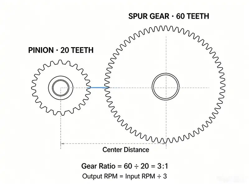
That is the whole magic. Nothing slips, nothing depends on friction — the teeth physically push each other. Efficiency on a single well-lubricated stage lands around 98–99%, which is why designers keep coming back to this arrangement even when the noise annoys them.
Where people run into trouble is the expectation of perfectly smooth motion. Spur gears engage and disengage abruptly. At high load or high speed, that abrupt engagement is what causes the characteristic whine, and it is also the reason design textbooks spend so much time on contact ratio and tooth profile modification.
Gear ratio: the math, with a real example
The gear ratio of a spur and pinion set is just the ratio of teeth on the driven gear to teeth on the driver:
Ratio = Number of teeth on driven gear ÷ Number of teeth on pinion
Or in speed terms: Output RPM = Input RPM ÷ Ratio
Worked example. A customer came to us last year with a packaging conveyor. Their motor runs at 1,450 RPM and they needed the drive roller around 480 RPM. The math:
1,450 ÷ 480 ≈ 3.0
So we designed a 3:1 pair: a 20-tooth pinion on the motor, a 60-tooth gear on the roller. The pinion sees roughly three times the load cycles of the gear, so we chose a harder material for it — 20CrMnTi through-hardened to HRC 58–62 — while the 60-tooth gear stayed on 45# steel, induction-hardened. That one material call saved the customer about 18% on the gear blank without shortening life.
A quick rule we hand to every junior engineer on the floor: below about 17 teeth on a 20° pressure angle, the pinion starts to undercut, and you lose material at the tooth root. Either add teeth, switch to a profile-shifted design, or go to a helical. Do not try to push a 12-tooth pinion through a 20° standard profile and expect it to last.
A short design guide: what we actually check on a drawing
When a drawing lands on our desk for a custom spur and pinion gear, we read it in this order:
- Module (or diametral pitch). This sets tooth size. In metric it is module m; in imperial it is diametral pitch DP. Mixing the two is the most common “why doesn’t this fit” support call we get.
- Number of teeth on each gear. This tells us the ratio and the center distance — the two dimensions that actually decide whether the pair will fit in the customer’s housing.
- Pressure angle. 20° is the modern standard. 14.5° still shows up on old American machinery and will not mesh with a modern 20° gear, so if the replacement is for a vintage machine, confirm before you quote.
- Material and heat treatment. Steel for heavy load, cast iron for a quiet running gear on a slow conveyor, nylon or acetal for food-contact or low-load hobbyist work. The choice drives both the price and the noise.
- Bore, keyway, and hub dimensions. The tooth profile is only half the job. If the bore or the keyway is wrong, the gear never gets mounted.
- Quality grade. For a general conveyor, an ISO-DIN 8–10 is plenty. For a precision positioning axis, you are looking at DIN 6 or tighter, which means grinding after hobbing and a price jump that surprises buyers.
If any of those six items is missing from the drawing, we call back before quoting. It saves everyone a round of rework.
Where spur and pinion drives actually show up
You will find pinion spur gears in places you would not necessarily think about:
- Packaging and bottling lines. The conveyor example above is a real order we shipped.
- 3D printer extruders. A small steel pinion on the stepper motor drives a larger brass gear; the ratio lets the motor push filament with real force without losing position.
- Rack and pinion in CNC machines. Turn the “gear” into a straight rack, and the same pair converts rotation into linear motion — this is how gantries move along X and Z.
- Garage door openers and electric gates. A multi-stage spur reduction between motor and drum, cheap and quiet enough for residential use.
- Watch movements and clock mechanisms. Even tiny clockwork is just a stack of pinion spur gears stepping the motion down.
When to pick something else
A spur and pinion is not always the right call. We tell customers to look elsewhere when:
- The speed is high and the noise is unacceptable — go helical.
- You need a ratio above about 6:1 in one stage — the big gear becomes comically large; split it across two stages.
- Shafts are not parallel — look at bevel, worm, or hypoid.
- You are weight-limited and torque is moderate — plastic gears may win on both cost and quiet.
FAQ
Q: Is a pinion gear and spur gear the same thing?
A: No. “Spur gear” describes the shape (straight teeth, parallel shaft). “Pinion” describes the role (the smaller gear in a mesh). Every pinion in a parallel-shaft pair is a spur gear, but not every spur gear is a pinion — the larger one is just the driven gear.
Q: What is the life expectancy of a spur and pinion gear?
A: It depends entirely on load, lubrication, and alignment. A well-designed, well-lubricated industrial pair running at 80% of its rated load will typically outlast the machine bolted to it. The classic failure we see is not wear — it is worn bearings letting the pinion walk out of mesh, which then chews up the teeth.
Q: Can I mix a metric spur gear with an imperial one?
A: Short answer: no. Module 2 and 12 DP look similar in size but the tooth shape is different. They will engage for a few revolutions and then strip.


