 +86 184 3796 0706
 info@destinytrans.com


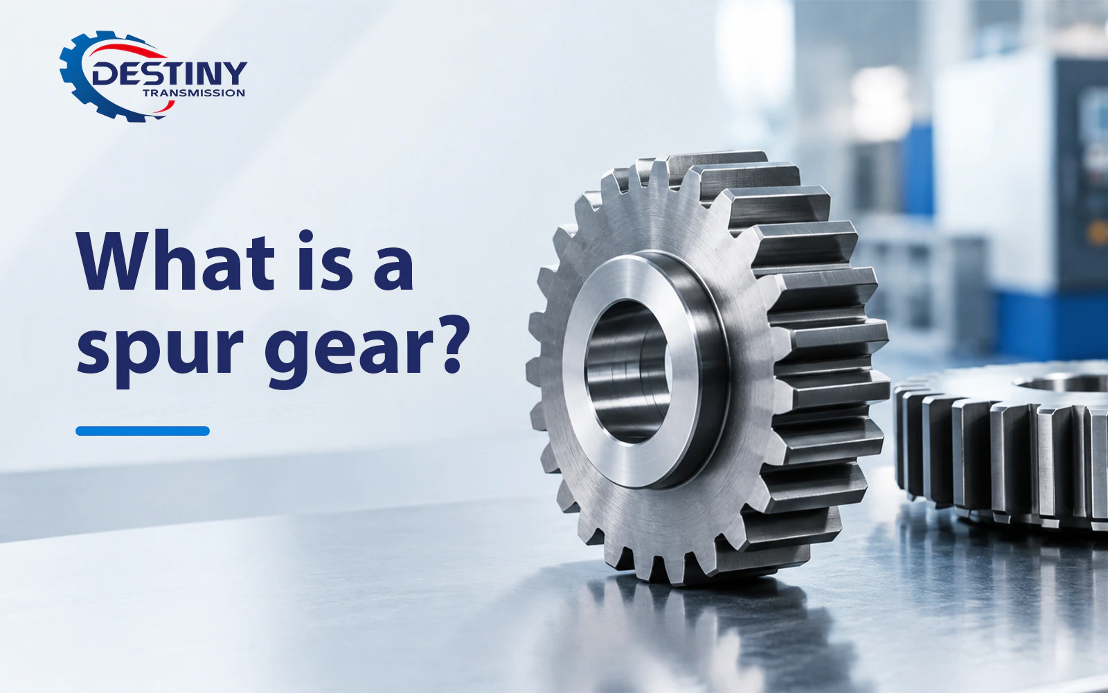
Walk into any manufacturing plant, take apart a household appliance, or disassemble a precision medical device, and you will almost always find spur gears running quietly and reliably inside. As the most widely used gear type in industry, their ubiquity is no accident. Built on a deceptively simple yet highly efficient transmission principle, they perform the core function of transmitting motion and power between parallel shafts.
Simplicity of design does not equal low technical merit. Whether a transmission system runs reliably for years or fails prematurely under load hinges largely on the design and specification of its spur gears. From basic parameters such as module and pressure angle to material grade and heat treatment process, every detail directly impacts the service life and reliability of the entire system. This guide provides a systematic overview of the fundamentals of spur gears, covering all key points engineers and procurement professionals need to know.
1.What is a spur gear?
Spur gears, formally known as spur cylindrical gears and sometimes called straight-cut gears, are the most common type of gear used in mechanical power transmission. Their defining structural feature is clear: the teeth have straight profiles and run exactly parallel to the gear’s central axis, designed specifically to transmit rotational motion and torque between two parallel shafts.
Unlike the gradual, smooth engagement of helical gears, spur gear teeth engage in a stepped, discrete contact pattern, making the meshing action direct and crisp. With their straight teeth cut parallel to the axis of rotation, spur gears typically achieve power transmission efficiencies of 95% to 99%, making them the most fundamental and well-established form of gearing available.
2. How spur gears work
Power transmission in spur gears relies on a precise tooth meshing mechanism. Behind their seemingly simple straight-tooth structure lies sophisticated geometric design and well-proven transmission logic.
2.1 Core transmission mechanism
Spur gears transmit power through the meshing of mating tooth pairs along their common pitch circle — the imaginary reference circle in gear design where the tooth profiles of two mating gears make effective contact.
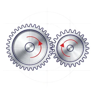
As the driving gear rotates, its tooth faces sequentially push against the tooth faces of the driven gear, smoothly transferring torque from one parallel shaft to the other. In a correctly matched gear pair, the driven gear always rotates in the opposite direction to the driving gear.
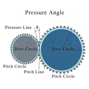
The entire meshing process follows an involute tooth profile, which is the core design advantage of modern industrial spur gears. This tooth geometry maintains a constant gear ratio throughout the full meshing cycle: the line of action remains tangent to the base circles of both gears at all times, resulting in smooth, predictable output angular velocity with no speed fluctuations during operation.
2.2 Key geometric features of spur gear teeth
Spur gear tooth design has three core characteristics that distinguish it from other gear types:
- Straight tooth profile: The teeth extend radially from the gear and run perfectly parallel to the central axis. This is the most visible identifying feature of spur gears and the primary difference between them and helical gears.
- Involute tooth form: Nearly all industrial-standard spur gears use an involute tooth profile to ensure a constant gear ratio. Cycloidal tooth profiles are now only used in specialty instruments such as clockwork mechanisms and have been largely phased out in power transmission applications.
- Full-face-width engagement: Because the teeth run parallel to the axis, they enter and exit contact across the entire face width simultaneously, rather than engaging gradually. This characteristic is responsible for both the high transmission efficiency of spur gears and their higher noise levels at high speeds.
2.3 Load characteristics and operating performance
The parallel tooth design of spur gears also defines their unique load behavior and suitable applications:
- Radial loads only: When meshing, spur gears generate only radial loads and produce no axial thrust on the shafts. This simplifies installation design, as only standard ball bearings are required — no additional thrust bearings needed, unlike with helical gears.
- Higher noise at high speeds: Because teeth engage and disengage across the full face width at once, the meshing action is abrupt with no smooth transition. As a result, vibration and noise at high operating speeds are generally higher than with helical gears.
For most general industrial applications, this noise level is perfectly acceptable. However, spur gears are typically not selected as the core transmission component in applications with extremely strict noise requirements, such as automotive main drive systems.
2.4 Main characteristics of spur gears
| Feature | Description |
| Tooth Profile | Spur involute tooth form, with tooth trace parallel to the gear axis |
| Shaft Arrangement | For parallel shaft applications only |
| Efficiency | 95–99% per meshing stage under good lubrication conditions |
| Axial Thrust | None — only radial loads are carried |
| Noise | Low noise at medium speeds; noise rises at high speeds due to abrupt tooth engagement |
| Manufacturing | Simple dual-axis cutting process; lower production cost than helical gears |
3. Parameter system and measurement standards for spur gear design
The specifications and transmission performance of every spur gear are defined by a set of precise geometric parameters. Whether selecting and purchasing gears, designing mating structures, or ordering custom machining, a solid understanding of these core parameters is essential to ensuring proper gear meshing, stable operation, and reliable performance.
3.1 Module vs. diametral pitch: two systems for measuring tooth size
Tooth size is a fundamental parameter of gear specification. Two dominant measurement systems are used in global industry — metric and imperial — and they cannot be mixed.
- Metric system: Module (m)Module is the core dimensional parameter for metric gears, defined as the ratio of the pitch circle diameter to the number of teeth, expressed in millimeters. For example, a gear with a 40 mm pitch circle diameter and 20 teeth has a module of 2 mm. Module value is directly proportional to the physical size of the teeth: the larger the module, the bigger the teeth and the higher the load capacity. A gear with module 4 has teeth roughly twice the size of a module 2 gear. Standard metric modules for general precision applications range from 0.5 to 4 mm, while larger modules are used for heavy-duty industrial drives.
- Imperial system: Diametral Pitch (DP)In the imperial system, tooth size is specified by diametral pitch, defined as the number of teeth per inch of pitch circle diameter. For example, a gear with 24 teeth and a 2-inch pitch circle diameter has a diametral pitch of 12 DP. Diametral pitch follows the inverse relationship to tooth size: the higher the DP value, the smaller the teeth. Common diametral pitches for commercial spur gears range from 6 to 48 DP.
Important note: Mating gears must use the same measurement system and have identical module / diametral pitch values, otherwise they cannot be properly assembled or transmit power.
3.2 Pressure angle: 20° vs. 14.5°
Pressure angle defines the direction of the force between meshing tooth surfaces. Specifically, it is the angle between the line of action on the tooth face and the tangent to the pitch circle at the point of contact. Two standard pressure angles dominate industrial use today:
- 14.5° pressure angle: An earlier industry standard, it offers smoother meshing and lower operating noise. Today it is mainly found in spare parts replacement for older equipment and maintenance of legacy machinery.
- 20° pressure angle: The current universal industry standard for new designs worldwide. A larger pressure angle creates a thicker tooth root structure, improving resistance to undercutting — an especially noticeable benefit for pinions with fewer than 17 teeth — while also increasing overall load capacity. Nearly all metric spur gears today use a 20° pressure angle.
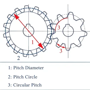
3.3 Pitch circle and pitch circle diameter
The pitch circle is an imaginary reference circle in gear design that serves as the baseline for determining tooth pitch and calculating all tooth profile parameters. Its diameter is known as the pitch circle diameter.
It is also the key parameter for determining the center distance between meshing gears: for a standard non-profile-shifted gear pair, the mounting center distance equals half the sum of the pitch circle diameters of the two gears.
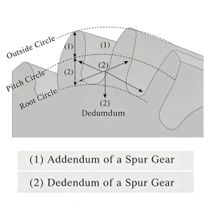
3.4 Addendum, dedendum and backlash
The radial height of a gear tooth is made up of the addendum and dedendum: the addendum is the radial height of the tooth profile extending outward from the pitch circle, while the dedendum is the radial depth of the tooth profile recessed inward from the pitch circle. Together they make up the total tooth depth.
A gear’s dedendum is typically slightly larger than the addendum of its mating gear. This creates necessary clearance at the tooth root to prevent jamming during operation and leaves space for lubricant to enter the contact zone.
Backlash is an often misunderstood parameter: it refers to the small clearance between the non-working faces of meshing gears, and is not a manufacturing defect.
Proper backlash is essential for normal gear operation. It compensates for thermal expansion during operation and ensures the formation of a lubricant film. Insufficient backlash causes tooth surface seizure, while excessive backlash increases vibration and positional error in the drive.
In applications with extremely high transmission accuracy requirements, such as industrial robots and CNC machine tools, spring-loaded anti-backlash dual gears are used to eliminate transmission play while preventing tooth jamming.
4. Profile shift design: an underrated engineering tool
In routine spur gear selection, most engineers simply specify standard gears with a profile shift coefficient x = 0 and proceed with structural design. However, profile shifting is a highly cost-effective engineering optimization that is too often overlooked.
By simply adjusting the radial position of the cutting tool relative to the gear blank during hobbing, it addresses two core challenges in transmission design without changing the number of teeth, module, or gear ratio.
4.1 Functional differences between positive and negative profile shifts
Depending on the direction of tool offset, profile shift designs are classified as positive or negative, each suited to different design requirements:
- Positive profile shift (x > 0): The cutting tool is offset away from the center of the gear blank. This produces gears with significantly thicker tooth roots, directly improving root bending strength and overall load capacity. More critically, it prevents undercutting in pinions with fewer than 17 teeth, making it a standard, cost-effective way to enhance the performance of small gears.
- Negative profile shift (x < 0): The cutting tool is offset toward the center of the gear blank, moderately reducing the overall meshing size of the gear. It is mostly used in space-constrained installations — when two shafts must be mounted inside a limited housing and standard gears cannot match the required center distance, negative profile shift can be used to meet fixed shaft spacing requirements.
4.2 Effect of profile shift on center distance
Profile shifting changes the actual meshing parameters of gears, so the calculation logic for mounting center distance differs accordingly:
- Standard gear pair (both gears with x = 0): Calculation is straightforward — the mounting center distance equals half the sum of the pitch circle diameters of the two gears.
- Profile-shifted gear pair (both gears with non-zero x): The operating pressure angle during meshing shifts. The actual operating pressure angle must be recalculated using the appropriate formula to determine the precise mounting center distance and ensure accurate assembly and transmission.
4.3 Key application scenarios
The value of profile shift design is particularly evident in compact transmission structures. For gearboxes with fixed internal shaft spacing or spare parts replacement for older equipment, off-the-shelf standard gears often struggle to meet both mounting dimensions and performance requirements simultaneously.
Profile shift design eliminates the need to modify the overall equipment structure. By adjusting only machining parameters, it achieves both dimensional compatibility and transmission performance, making it a lightweight optimization solution that balances cost and effectiveness.
5. Types of spur gears
Spur cylindrical gears can be categorized by meshing type, structural form, design approach, manufacturing precision, and material properties. Each category suits different transmission requirements, mounting scenarios, and operating conditions, making these fundamental dimensions to define during the selection process.
5.1 Classification by meshing type (most fundamental classification)
This is the most essential way to categorize spur gears, as it directly determines the transmission configuration and motion output:
- External meshing spur gears The most common type of spur gear in industry, consisting of two external-tooth gears meshed together. When operating, the two gears rotate in opposite directions. With simple construction and easy manufacturing, they are widely used in reducers, conveying equipment, gear pumps, and most other parallel shaft transmission applications.
- Internal meshing spur gears Consist of an external gear paired with an internal gear ring. When operating, both gears rotate in the same direction, and the overall assembly is compact with a small footprint. They are a core component of planetary gear reduction mechanisms and are heavily used in power tools, precision gearboxes, and other applications with strict space constraints.
- Spur gear and rack assemblies Consist of a spur gear paired with a straight rack, converting the gear’s rotational motion directly into linear motion of the rack (or vice versa). With a constant transmission ratio and controllable positioning accuracy, they are widely used in CNC machine tool axis drives, elevator lifting mechanisms, automotive steering systems, and other linear motion control applications.
5.2 Classification by structural form
Categorized by the gear’s body structure and mounting style, to suit different size specifications and load ratings:
- Solid spur gears The gear body is solid. Mostly used for micro and small gears with small modules and diameters, they offer high overall strength and low manufacturing complexity, and are common in light-load drives for instruments, small home appliances, and precision electronic equipment.
- Web-type spur gears The dominant structure for medium-sized gears, with a flat web between the rim and hub. Lightening holes are often drilled to reduce weight while maintaining structural strength. This is the most common structural form in industrial reducers and general-purpose machinery.
- Spoked spur gears A gear structure for large-diameter, heavy-duty applications, with spokes connecting the rim and hub. This significantly reduces the weight and material cost of large gears, and is mostly used in large industrial drives such as mining machinery and heavy lifting equipment.
- Assembled spur gears Also known as split gears, with the rim and hub as separate components assembled by bolts, interference fits, or other methods. They simplify transportation, installation, and maintenance of large gears. The rim can be replaced independently when worn, effectively reducing the total lifecycle cost of equipment.
Additionally, based on mounting bore type, gears come in plain bore, keyway bore, spline bore, set screw bore, and other configurations to suit different shaft connection requirements.
5.3 Classification by profile shift design
Categorized by the radial tool offset during hobbing, corresponding to different design optimization needs:
- Standard spur gears (profile shift coefficient x = 0) The most common standard specification, with no radial tool offset. Parameters comply with universal industry standards, mass production is readily available, costs are predictable, and they suit the vast majority of general industrial transmission applications.
- Positive profile shift spur gears (x > 0) The cutting tool is offset away from the gear blank center, significantly increasing tooth root thickness. This effectively prevents undercutting in low-tooth-count gears and improves bending load capacity, making them ideal for small heavy-duty gears and reinforced transmission designs.
- Negative profile shift spur gears (x < 0) The cutting tool is offset toward the gear blank center, reducing the meshing center distance. They suit special scenarios with limited installation space and fixed housing shaft spacing.
5.4 Classification by manufacturing precision and process
Different manufacturing processes correspond to different accuracy grades and application scenarios:
- Hobbed / shaped spur gears General-purpose machining process, typically AGMA grade 4 to 6. They offer high production efficiency at moderate cost, meeting the needs of most conventional industrial transmissions.
- Ground spur gears High-precision gears finish-ground after heat treatment, achieving AGMA grade 6 to 8. They provide smoother operation and lower noise, making them suitable for precision robotics, CNC machine tools, high-speed drives, and other applications with high accuracy and quietness requirements.
- Cold-formed / powder metallurgy spur gears Formed in one step by cold extrusion or powder metallurgy, they are suitable for high-volume mass production at low cost. Mostly used in light-load consumer applications such as home appliances, consumer electronics, and toys.
5.5 Classification by material
Categorized by the gear body material, corresponding to different operating environments and load requirements. The main categories are carbon steel spur gears, hardened alloy steel spur gears, stainless steel spur gears, aluminum alloy spur gears, and engineering plastic spur gears. For specific properties and suitable applications, refer to the material selection section.
6. How to choose materials for spur gears: a complete guide for different operating conditions
Material selection is a core part of spur gear design and specification. It directly affects load capacity, operating noise, weight, corrosion resistance, and overall cost. Material requirements vary significantly across applications: for example, gear material for a food processing conveyor line follows very different standards than that for an aerospace actuator.
| Material | Key Characteristics | Typical Applications | Notes |
| Carbon Steel (S45C / 1045) | High strength and wear resistance; induction hardenable to approx. HRC 55 | Heavy machinery, conveying equipment, gear reducers, gear pumps | One of the most widely used materials for industrial gears, offering a balance of cost efficiency and good machinability |
| Stainless Steel (SUS303 / 304 / 316) | Corrosion resistant (minimum 11% chromium content); 303 provides better machinability, 316 is suited for chemical corrosion resistance | Food processing, medical equipment, pharmaceutical equipment, chemical plants | For gears meshing with plastic parts, stainless steel is recommended on one side to offset thermal expansion effects |
| Alloy Steel (Hardened) | Excellent fatigue resistance; ground teeth achieve AGMA quality grade 6–8 | Gearboxes, automotive, aerospace systems under heavy-duty cyclic loading | Grinding after heat treatment corrects deformation caused by the hardening process |
| Aluminum Alloy (6061 / 7075) | Roughly 1/3 the weight of steel; good corrosion resistance; 7075 delivers high strength via zinc/magnesium alloying | Aerospace, hand tools, robotics and other weight-sensitive applications | Higher cost per kilogram than steel, but easier to machine |
| POM / Nylon / PEEK | Light weight, quiet operation, self-lubricating, corrosion resistant | Office automation, home appliances, toys, electronics, medical equipment | Not suitable for high-torque applications; PEEK withstands higher temperatures than POM or nylon |
Spur gears can be manufactured by a variety of processes, including hobbing, shaping, cold forming, and precision grinding, each suited to different accuracy grades and production volumes.
7. Key comparison: spur gears vs. helical gears and how to choose
Spur gears and helical gears are the two most widely used gear types for parallel shaft transmission. Neither is inherently superior; the right choice depends on a combination of noise tolerance, actual load and speed requirements, and project budget.
Spur gears achieve transmission efficiencies of 95% to 99%, generate no axial thrust during meshing, and have relatively lower manufacturing costs, making them the standard choice for most industrial drive systems.
| Spur Gear Tooth Profile | Helical Gear Tooth Profile |
| Straight tooth trace, parallel to the gear axis | Helical tooth arrangement with a defined helix angle |
| Full face width engagement simultaneously | Progressive, continuous meshing action |
| High efficiency, no axial thrust generated | Quieter operation, but generates axial thrust |
By comparison, helical gears engage gradually, resulting in smoother operation and lower noise, making them better suited for high-speed, high-load transmission conditions. However, helical gears generate axial thrust when meshing, placing higher demands on bearing selection, and their overall manufacturing cost is higher than spur gears.
8. Where are spur gears used? Five key application areas
With their efficient, reliable transmission performance and strong adaptability, spur gears are one of the most widely used gear categories today. From precision micro instruments to heavy industrial drive systems, reliable power transmission can be achieved with spur gears. Their core applications fall into five main categories:
Industrial mechanical drives
Industrial machinery is the primary application for spur gears. Conveying systems, industrial reducers, gear pumps, and the core drive trains of machine tools all commonly use spur gears as key transmission components. In reducer configurations, multiple spur gear pairs arranged in series reduce motor output speed while amplifying torque. They also allow a single motor to drive multiple drive shafts simultaneously, effectively simplifying system architecture and controlling overall equipment cost.
Precision drives for robotics and automation
In high-precision automation and robotics, precision ground spur gears and anti-backlash gear assemblies are standard. They are widely used in industrial robot joints, CNC positioning systems, semiconductor manufacturing equipment, and other applications requiring extremely high repeatability. Planetary gearboxes made up of spur gear sets deliver high torque output within the compact installation space of robot joints, perfectly matching the demand for small form factors and high loads.
Food and medical cleanroom applications
For applications requiring corrosion resistance and sanitary standards, stainless steel (SUS303 / SUS316) spur gears are the mainstream choice, suitable for food processing conveyor lines, pharmaceutical filling equipment, medical device actuators, and other cleanroom environments. For special applications where metal materials still pose a contamination risk, POM or PEEK plastic spur gears with stainless steel inserts offer an alternative. They combine corrosion resistance and self-lubrication to meet the requirements of specialized scenarios.
Consumer products
Home appliances, office equipment, power tools, and other consumer products commonly use spur gears made of plastic or light alloy — for example in washing machines, dryers, food processors, office printers, and handheld power tools. Spur gears perform the functions of motor speed reduction and torque amplification in these products. Small plastic spur gears have low manufacturing costs and are easy to mass produce, offering excellent cost-effectiveness in consumer applications with moderate torque loads and relatively relaxed noise requirements.
Positioning and linear motion control
Gear-rack assemblies consisting of a spur gear and rack convert rotational motion into precise linear motion. They are extensively used in CNC machine tool axis drives, industrial robot traversing mechanisms, elevator lifting systems, and automotive steering rack systems. The constant gear ratio of spur gears makes motion during transmission highly predictable. For applications where positioning accuracy is the priority, this predictable transmission characteristic is more valuable than smoothness of operation.
9. Core advantages and limitations of spur gears
Spur gears are the most classic fundamental transmission solution in industrial power transmission. Their widespread adoption stems from several irreplaceable performance advantages, but they also have clear application limits. Fully understanding their strengths and weaknesses during the selection phase is essential to matching them accurately to operating conditions and maximizing transmission system performance.
Core advantages
- Excellent transmission efficiency Spur gears typically achieve 95% to 99% transmission efficiency, placing them among the highest-performing gear types. Power loss during transmission is extremely low, making them suitable for industrial drive systems with strict efficiency targets.
- Simple load structure Only radial loads are generated throughout meshing, with no axial thrust. No additional thrust bearings are required, greatly simplifying bearing selection and housing design, and reducing engineering and material costs.
- Constant, precise gear ratio Thanks to their involute tooth profile, spur gears maintain a stable gear ratio throughout the meshing cycle, delivering smooth, predictable output speed. This makes them ideal for motion control applications requiring high positioning accuracy and consistent transmission.
- Cost-effective mass production With a mature tooth geometry and simple manufacturing process, spur gears cost significantly less to produce at scale than complex tooth forms such as helical gears, making them a cost-effective choice for medium and light load transmission applications.
- Comprehensive standardization Full ranges of standard metric modules and imperial diametral pitches are available, with a wide selection of materials and hub configurations. Market supply is abundant, leading to short procurement and spare parts lead times.
- Easier operation and maintenance Installation, commissioning, routine maintenance, and spare parts replacement are straightforward, with no complex alignment required. This effectively reduces operation and maintenance costs over the equipment lifecycle.
- Strong load adaptability Spur gears with properly designed parameters and matching heat treatment hardening can reliably handle heavy load conditions. A contact ratio of 1.2 to 1.6 is sufficient to meet load distribution requirements in most industrial scenarios.
Application limitations
- Higher noise at high speeds Teeth engage and disengage across the full face width simultaneously, making the meshing action abrupt. Vibration and noise at high speeds are noticeably higher than with helical gears, making them unsuitable for high-speed transmission applications with strict quietness requirements.
- Lower tooth surface stress limit Due to their lower contact ratio, spur gears experience higher tooth contact stress than helical gears under the same load, resulting in certain limits to their ultimate load capacity.
- Limited transmission configurations They can only transmit power between parallel shafts and cannot accommodate crossed or perpendicular shaft arrangements, restricting their use to certain structural layouts.
- Strict installation accuracy requirements Center distance accuracy between the two shafts must be high. Compared with flexible drives such as belt drives, there is less flexibility for center distance adjustment, and assembly errors directly affect meshing performance and gear service life.
- Inherent backlash in standard designs Conventional standard spur gear pairs naturally have transmission backlash. Achieving zero-backlash precision transmission requires additional special components such as anti-backlash gears, which increases structural complexity and cost.
10. How to select spur gears: a complete guide from parameters to materials
Matching the right spur gear to a specific application does not require complex trial and error. Following a standardized checklist of core parameters allows efficient selection and avoids common issues such as meshing failure, insufficient load capacity, and unnecessary cost overhead.
1. Define the target gear ratio
The gear ratio is the starting point for gear selection, directly determining the tooth count ratio between the driving and driven gears. For example, a 2:1 reduction drive means the driving gear has half the teeth of the driven gear, achieving lower speed and higher torque.
After confirming the drive direction (reduction or increase) and target gear ratio, use a gear ratio calculator to verify the suitability of the tooth count combination before proceeding with further parameter selection.
2. Select module or diametral pitch specification
Module (metric) and diametral pitch (imperial) are the core parameters determining tooth size and load capacity limit. They should be selected based on both torque transmission requirements and available installation space. Larger module values mean physically bigger teeth and higher load capacity, but also require more mounting space.
Important note: Mating gears must use the same measurement system and have identical module / diametral pitch values, otherwise they cannot mesh properly.
3. Match the pressure angle standard
Pressure angle selection follows the principle: “use the new standard for new designs, match the original standard for spare parts replacement.”
For newly designed transmission systems, the globally standard 20° pressure angle is the default, offering higher tooth root strength and better undercut resistance. Only when replacing existing gears in older equipment is it necessary to match the original 14.5° pressure angle specification to ensure meshing compatibility.
4. Select gear material according to requirements
Material selection should correspond to the operating environment and torque load level:
- General industrial heavy-duty: Prioritize hardened carbon steel for a balance of strength and cost.
- Corrosion-resistant cleanroom: Stainless steel for food, medical, and chemical applications.
- Lightweight requirements: Aluminum alloy for aerospace, handheld tools, and other weight-sensitive applications.
- Light-load, low-noise: Engineering plastics offer better cost-effectiveness for low-load applications such as consumer home appliances and office equipment.
5. Match manufacturing precision grade
Different manufacturing processes correspond to different accuracy grades and application scenarios. For precision drives with high-speed operation and low noise requirements, high-precision ground gears (AGMA grade 6–8) are recommended. For general industrial conditions, hobbed or cold-formed gears are sufficient, balancing performance and procurement cost.
6. Determine hub and bore configuration
The connection type of the hub and mounting bore should be selected based on transmitted torque magnitude, shock load intensity, and maintenance frequency. Common options include keyways, splines, set screws, and split hubs. Higher loads and stronger shocks require more secure connection solutions to ensure long-term transmission reliability.
7. Confirm backlash and profile shift strategy
For general industrial transmission, standard gears with manufacturer-standard backlash are sufficient. For precision positioning and high-accuracy drives, zero-backlash gear assemblies should be specified.
If the housing’s mounting center distance is constrained by space, profile shift optimization should be evaluated first. It can meet established mounting dimensional requirements without modifying the housing structure.
FAQ
Below are expert answers to common questions about spur gear selection and application, to help clarify key concepts and selection logic.
1. What is the difference between module and diametral pitch?
Both are core parameters describing tooth size, each belonging to a separate measurement system.
The metric system uses module (m), calculated as pitch circle diameter (mm) divided by number of teeth. A higher value means larger teeth and higher load capacity.
The imperial system uses diametral pitch (DP), calculated as number of teeth divided by pitch circle diameter (inches). A higher value means smaller teeth.
Mathematically they can be converted using the formula module × DP ≈ 25.4, but they are separate standard systems and cannot be mixed. Mating gears must use the same system with identical module / diametral pitch values.
2. Why do spur gears make more noise at high speeds?
This is determined by the tooth geometry of spur gears. The teeth run perfectly parallel to the axis, so they enter and exit contact across the full face width simultaneously, resulting in impact meshing. Repeated tooth impacts induce structural vibration, which produces noticeable operating noise.
Helical gears achieve gradual engagement through their angled teeth, greatly reducing meshing impact and noise. However, this comes at the cost of axial thrust, increasing the complexity of bearing selection and housing design.
3. Can spur gears be used without lubrication?
Standard metal spur gears must operate with lubrication. Lubrication effectively reduces the coefficient of friction on tooth surfaces, removes heat generated during operation, and slows tooth wear. Running under dry friction rapidly accelerates tooth surface fatigue and pitting failure, significantly shortening gear service life.
The only exception is engineering plastic spur gears. Materials such as POM and some nylons have inherent self-lubricating properties and can run dry. They are often used in food processing, medical devices, and other applications with special cleanliness requirements.
4. What are profile-shifted gears? When is profile shift design appropriate?
Profile shifting is an optimization technique in gear hobbing: by radially adjusting the relative position of the cutting tool and gear blank, it modifies tooth geometry parameters without changing module, number of teeth, or gear ratio.
It is primarily suited to two core scenarios:
First, positive profile shift, which thickens the tooth root and improves bending load capacity, while also preventing undercutting in 20° pressure angle pinions with fewer than 17 teeth.
Second, matching fixed center distances: when housing shaft spacing is fixed and standard gears cannot fit perfectly, profile shift design adjusts meshing dimensions without modifying the housing structure.
5. What is the typical transmission efficiency of spur gears?
A single-stage spur gear pair in good lubricated condition typically achieves 95% to 99% meshing efficiency, placing it among the highest-performing gear transmission types.
Note that the overall efficiency of multi-stage gearboxes decreases with each stage. For example, if a two-stage gearbox has 98% efficiency per stage, the total system efficiency is approximately 96%.
6. When should helical gears be preferred over spur gears?
There are three main scenarios where helical gears are preferable:
First, applications with extremely strict noise and vibration requirements, such as passenger vehicle drivetrains and HVAC systems.
Second, high-load, high-speed operating conditions where higher contact ratio is needed to distribute tooth surface stress.
Third, non-parallel shaft transmission layouts.
For conventional parallel-shaft industrial drives with moderate noise tolerance, spur gears offer simpler construction, higher transmission efficiency, and lower procurement and maintenance costs, making them the more cost-effective choice.
Conclusion
Spur gears are the most representative fundamental transmission components in modern industrial drive systems. Based on the simple, well-proven straight-tooth involute design, they deliver highly efficient power transmission of 95% to 99%, while offering multiple advantages including simple load structure, easy installation and maintenance, comprehensive standard specifications, and controllable mass production costs. This allows them to cover transmission needs across all scenarios, from precision consumer electronics and food/medical cleanroom equipment to heavy industrial reducers and high-precision automation robots.
However, spur gears are not a “one-size-fits-all” solution for every application. Their inherent tooth geometry makes them better suited to parallel shaft arrangements, medium-to-low speed operation, and scenarios with moderate noise tolerance. For requirements involving high-speed quiet operation, heavy shock loads, or non-parallel shaft drives, other transmission forms such as helical gears are often a more rational choice.
For specifiers, the core principle of spur gear selection is application-first, needs-based matching: start with basic parameters such as gear ratio, module/diametral pitch, and pressure angle; match material and manufacturing precision to actual load levels and operating environment; then determine whether advanced optimizations such as profile shift design or anti-backlash components are needed based on installation space constraints and transmission accuracy requirements. There is no need to blindly pursue higher parameters or material grades that create unnecessary cost overhead, nor should selection standards be lowered to save budget, which risks premature failure.
The complete selection logic and parameter details can be verified item by item against the selection checklist earlier in this guide. For custom requirements involving special mounting dimensions or unique operating conditions, optimization techniques such as profile shift design and specialty material processes can achieve the optimal balance between transmission performance and installation requirements, while controlling overall cost.


