 +86 184 3796 0706
 info@destinytrans.com



In industrial transmission systems, gear design affects more than torque transmission and speed changes. It also influences operating stability, transmission noise, load capacity and service life. When standard gears cannot meet specific requirements for installation space, gear ratio, load or component fit, custom gear design becomes an important part of machinery development and transmission component improvement.
For engineers, custom gear design involves more than selecting the module, number of teeth and overall dimensions. Actual operating loads, shaft arrangement, material properties, heat treatment, gear accuracy and downstream manufacturing processes must all be considered within a coordinated set of technical requirements. Even if an individual parameter meets its design target, that does not guarantee that the gear will operate properly once installed in the equipment.
A sound custom gear design process therefore starts with actual operating conditions and brings structural parameters, manufacturing processes and quality inspection requirements together. This approach helps improve compatibility between the gear and the equipment while reducing machining rework, assembly problems and unnecessary manufacturing costs.
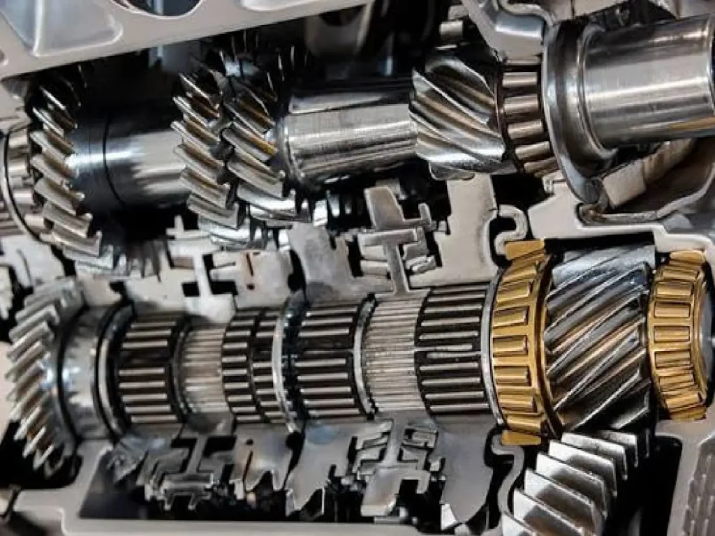
1. Define the Application and Operating Conditions
Operating conditions are the starting point for custom gear design. The required torque, operating speed, load conditions and expected operating hours all influence the gear’s structural design and performance requirements.
Engineers should first establish the rated torque, rotational speed, transmission power, load variations, start-stop frequency and expected service life. For equipment that starts and stops frequently or experiences impact loads, the design must account for peak loads and their duration rather than relying on rated power alone. For transmission systems that operate continuously over long periods, tooth surface wear, contact fatigue, tooth root bending fatigue and lubrication conditions require particular attention.
The operating environment also affects the design. High temperatures can change lubricant properties, dust can accelerate tooth surface wear, and moisture or corrosive substances can affect material selection and surface protection. For equipment with limited installation space, engineers must also verify the clearances between the gear and adjacent components, including shafts, bearings, housings and other parts, throughout operation.
When a gear is intended to replace an existing component, the actual operating condition of the original transmission system should also be assessed. Abnormal noise, localized wear or repeated failures may be related to load distribution, shaft alignment, lubrication or assembly conditions. Simply copying the original gear dimensions may not resolve these problems.
Defining the operating conditions and performance objectives before design begins provides a reliable basis for selecting the gear type, calculating strength requirements and evaluating materials.
2. Select the Appropriate Gear Type and Transmission Parameters
2.1 Compare Different Gear Types and Their Applications
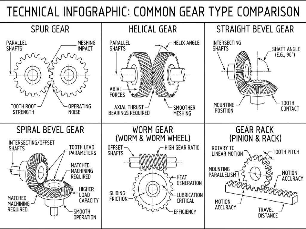
The gear type determines the basic structure of the transmission system and influences load distribution, operating smoothness, bearing loads and manufacturing requirements. Engineers should select a suitable design based on shaft arrangement, transmission direction, gear ratio, installation space and operating conditions.
Common gear types and their design considerations are summarized below.
| Gear Type | Typical Applications | Key Design Considerations |
|---|---|---|
| Spur gears | Power transmission between parallel shafts; relatively simple construction | Meshing impact, tooth root strength and operating noise |
| Helical gears | Generally provide smoother meshing and suit various parallel-shaft applications | Axial forces, helix angle and bearing load capacity |
| Straight bevel gears | Power transmission between intersecting shafts | Shaft angle, mounting position and tooth contact |
| Spiral bevel gears | Applications with specific requirements for spatial transmission, load capacity and smooth operation | Tooth contact, tooth lead parameters, matched machining and assembly requirements |
| Worm and worm wheel | Applications requiring specific shaft arrangements or relatively high gear ratios | Sliding friction, heat generation, lubrication and efficiency |
| Gear racks | Conversion between rotary and linear motion | Tooth pitch, mounting parallelism, motion accuracy and travel distance |
2.2 Determine Compatible Gear Parameters
After selecting the gear type, engineers must coordinate parameters such as module, number of teeth, pressure angle, helix angle, face width, center distance and gear ratio. These parameters are interdependent and cannot be determined entirely in isolation.
The module and number of teeth jointly affect the main gear dimensions and gear ratio, while face width must be determined by considering load, tooth contact conditions, shaft stiffness and installation space. When designing helical gears, the helix angle and the relationships between normal and transverse parameters must be clearly defined. Bevel gear design, in contrast, requires careful consideration of the shaft angle, tooth surface geometry and mating conditions. Parameter selection should prioritize proper meshing and actual load requirements rather than adjusting a single dimension independently.
If a custom gear must mesh with an existing gear, engineers must also verify the mating gear’s module or normal module, pressure angle, number of teeth, helix hand and relevant mounting parameters. For bevel gears and other specialized designs, the shaft angle, tooth surface geometry and mating relationship must also be checked.
The goal of custom gear design is not to optimize a single dimension in isolation, but to ensure that the entire transmission system operates as intended.
3. Choose Suitable Materials and Heat Treatment Processes
3.1 Select Gear Materials Based on Operating Conditions
Material selection directly affects gear strength, wear resistance, fatigue performance and manufacturing cost. Different materials have different hardness, toughness, heat treatment responses and machinability. Selection should therefore reflect the load, operating environment, component dimensions and expected service life rather than simply pursuing higher hardness.
Common gear materials include carbon steel, alloy steel and cast iron. Carbon steel is suitable for many general transmission applications. Depending on the grade, heat treatment condition and design requirements, alloy steel can provide the required combination of strength and wear resistance. Cast iron may be appropriate for certain designs where castability, vibration damping or cost is a consideration, although its suitability must still be verified through load and structural assessments.
3.2 Choose an Appropriate Heat Treatment Process
For gears subject to heavy loads or long operating periods, the heat treatment process is particularly important.
Carburizing and quenching: Suitable for certain gears that require high surface hardness and wear resistance while retaining adequate core toughness.
Quenching and tempering: Improves the overall mechanical properties of the material through quenching followed by high-temperature tempering. The actual results depend on the material grade and process conditions.
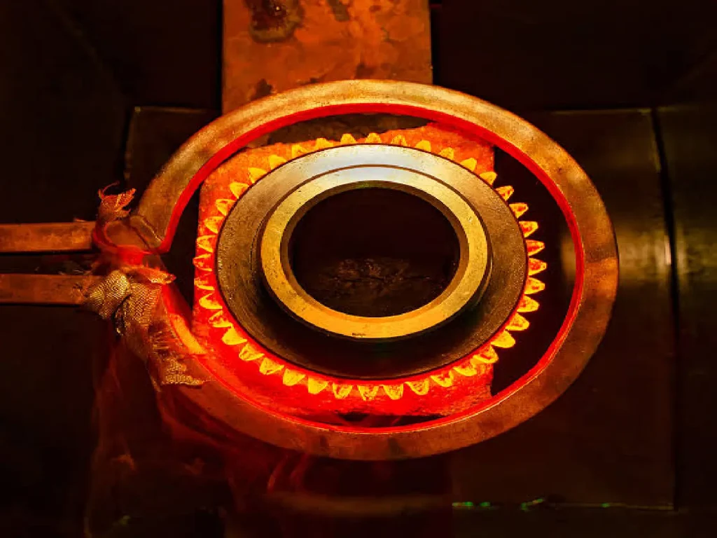
Induction hardening: Can be used to harden the surface of suitable materials and component designs. Process feasibility must be assessed according to tooth geometry, component dimensions and hardening requirements.
The specific process should also account for hardenability, cross-sectional dimensions, target hardness and deformation control. For gears requiring high tooth surface accuracy, engineers should evaluate dimensional changes after heat treatment and determine whether subsequent finish machining will be necessary. This helps prevent conflicts between final accuracy requirements and the manufacturing route.
3.3 Consider Gear Failure Risks and Post-Treatment Accuracy
Material selection and heat treatment should be based on the gear’s potential failure modes. Contact fatigue and wear may require enhanced surface properties, while tooth root bending loads demand sufficient overall strength and toughness. Different failure risks may call for different material and heat treatment solutions.
Heat treatment can also cause dimensional changes and distortion, affecting tooth profile, tooth lead, radial runout and other critical dimensions. Engineers should therefore define the material, heat treatment requirements and subsequent finishing route during the design stage. Additional processes, such as gear grinding, may be necessary to achieve the final accuracy requirements.
4. Define Gear Accuracy and Tolerance Requirements
4.1 Understand Gear Accuracy Requirements
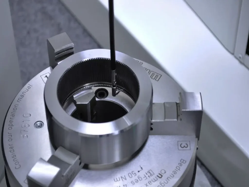
Gear accuracy affects meshing quality, transmission error, operating noise and motion positioning performance. In high-speed transmissions, precision positioning mechanisms and equipment requiring smooth operation, deviations in tooth surface geometry can become important factors affecting overall system performance.
Gear accuracy requirements vary by application. For a conveyor drive, engineers need to consider operating speed, load, noise limits and expected service life when setting accuracy targets. A high-speed servo drive may require tighter control of transmission error, tooth profile and tooth lead to support precise motion and smooth operation. Depending on the design requirements, gear grinding may also be necessary to achieve the specified accuracy.
4.2 Select Applicable Standards and Tolerances
Engineers can refer to applicable accuracy standards according to the gear type and application. For example, ISO 1328-1:2013 specifies a classification system and associated permissible values for flank tolerances of cylindrical involute gears. Bevel gears, worm gears and other gear types require evaluation methods based on their respective product standards and technical requirements. Accuracy grades from different standards should not be assumed to be directly equivalent.
Gear accuracy grades should not be specified without considering the intended function. Tolerances that are too loose may result in inadequate meshing or assembly performance. Unnecessarily tight tolerances, on the other hand, can increase machining, inspection and manufacturing costs without necessarily improving the performance of the complete machine.
A more effective approach is to identify the critical characteristics that require control and ensure that the engineering drawings, tolerance requirements and inspection methods are consistent with one another. For applications requiring high accuracy, the applicable standard, inspection equipment, acceptance criteria and measurement methods should be confirmed in advance.
Destiny Transmission can evaluate precision machining requirements according to the gear type, drawing specifications and applicable standards. For projects with defined accuracy grades, customers are encouraged to provide the relevant drawings and acceptance criteria during technical discussions so that machining capabilities and inspection requirements can be assessed together.
For more information about specific gear types and related manufacturing services, visit the gear products page.
5. Consider Manufacturability from the Design Stage
A gear may meet every design requirement on paper and still be difficult or expensive to manufacture. The core principle of design for manufacturability (DFM) is to ensure that structural parameters, tolerance requirements and machining processes work together while meeting functional requirements.
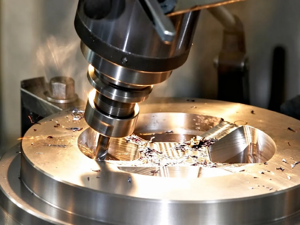
Tooth geometry, face width, bore diameter, shaft journals, keyways and other structural features can affect machining methods, workholding arrangements and inspection difficulty. For gears with specialized tooth profiles or complex structures, engineers must also confirm that the available equipment, cutting tools and machining routes can meet the requirements.
Tolerance design is an important part of this process. Critical dimensions that affect installation and meshing should have clearly defined tolerances. Non-critical dimensions that do not affect function should not automatically be assigned unnecessarily tight tolerances. This helps control machining and inspection costs without compromising product performance.
Process sequencing also needs to be considered during design. If a gear requires grinding or other finish machining after heat treatment, engineers should evaluate heat treatment distortion, machining allowances and the methods used to control final dimensions in advance. For gears with specialized structures, accessibility for workholding, machining and inspection must also be assessed.
For example, when a gear requires strict tooth surface accuracy, the design team must specify the final accuracy requirements and confirm the corresponding machining route and inspection method with the manufacturer. If the design focuses only on final dimensions without considering heat treatment distortion and finishing requirements, production may later encounter rework or fail to meet acceptance criteria.
Before moving a project into mass production, the engineering and manufacturing teams should review the drawings, materials, heat treatment requirements, critical tolerances and inspection items together. Confirming these details early helps identify manufacturing risks and reduces the need for later design changes.
6. Prepare Complete Technical Documentation for Custom Gear Manufacturing
Complete technical documentation directly affects how well the manufacturer understands the product requirements. It also influences quotation accuracy, process evaluation and delivery lead time. For non-standard gears, providing only the outside diameter, number of teeth or a drawing that lacks critical parameters is generally insufficient for an accurate technical assessment.
If engineering drawings are available, provide the following information:
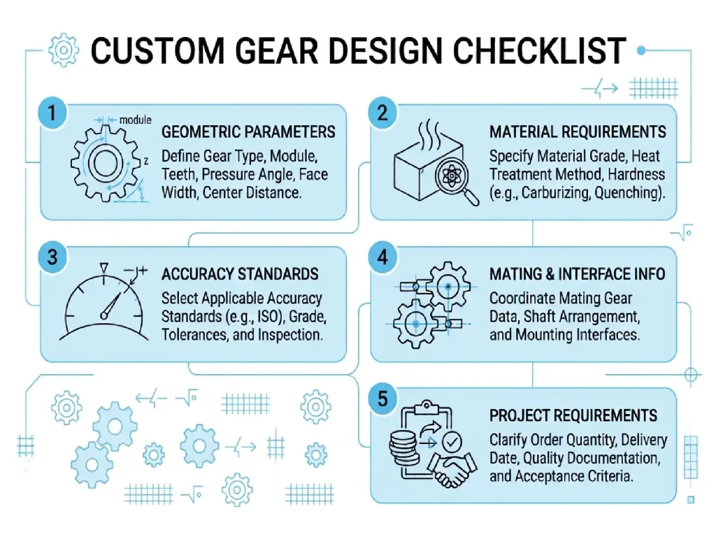
Geometric parameters: Gear type, module, number of teeth, pressure angle, face width, center distance and other critical dimensions.
Material requirements: Material grade, heat treatment method, hardness requirements and any necessary surface treatment.
Accuracy requirements: Applicable standards, accuracy grade, critical tolerances and inspection requirements.
Mating and interface information: Mating gear parameters, shaft arrangement, mounting interfaces and relevant assembly requirements.
Project requirements: Order quantity, expected delivery date, quality documentation and special acceptance criteria.
Not every gear requires exactly the same set of parameters. For example, helical gears require attention to the helix angle and related geometric parameters, while bevel gears require additional information about the shaft angle and mating relationship. Technical documentation should be tailored to the specific gear type and application.
If complete drawings are not yet available, existing samples, basic dimensions, equipment photos, installation conditions and operating parameters can be provided for an initial technical assessment. However, a sample provides only a geometric reference. It does not, by itself, establish the original design’s load capacity, material condition or actual accuracy. For worn or deformed parts, engineers must also determine whether the measured dimensions represent the original design.
Order quantity, target delivery date and acceptance criteria should also be clarified as early as possible to support purchasing and production planning. For repeat orders, maintaining consistent drawing revisions, material requirements and inspection standards helps prevent misunderstandings between production batches.
7. Common Custom Gear Design Mistakes and Their Consequences
Problems in custom gear projects are rarely caused by a single parameter alone. They often arise when operating conditions, design parameters, manufacturing capabilities and inspection requirements are not properly coordinated.
The following issues deserve particular attention during design reviews.
|
Common Design Mistake |
Potential Consequences |
Recommended Improvement |
|
Focusing only on external dimensions while ignoring mating parameters |
Improper meshing or abnormal tooth contact |
Verify the mating gear geometry, helix hand and mounting conditions |
|
Failing to account adequately for impact loads or load variations |
Tooth root fatigue, tooth surface damage or premature failure |
Evaluate strength and service life under actual operating conditions |
|
Pursuing high hardness without considering overall material properties |
Insufficient toughness or a heat treatment solution that does not match the actual load |
Assess material grade, hardness, heat treatment and failure risks together |
|
Applying excessively tight tolerances to every dimension |
Increased machining difficulty, inspection costs and lead time |
Distinguish critical from non-critical dimensions and allocate tolerances appropriately |
|
Failing to define post-heat-treatment machining and inspection requirements |
Dimensional deviations, inadequate tooth surface accuracy or rework |
Establish the machining route, allowances and acceptance criteria in advance |
|
Omitting critical inspection requirements from the drawings |
Some dimensions may meet specifications while functional performance or overall quality remains insufficiently verified |
Specify critical inspection items in the drawings or technical agreement |
These issues demonstrate why gear design must go beyond defining geometric dimensions. Design parameters must remain consistent with actual operating conditions, manufacturing processes and final acceptance criteria.
For projects involving complex structures, heavy loads or strict accuracy requirements, a technical review before production is recommended. Particular attention should be paid to mating conditions, material and heat treatment, critical tolerances and inspection methods. Identifying potential risks before manufacturing is generally more effective than revising the design after trial assembly or operation.
FAQ: Common Questions About Custom Gear Design
1. What information is required for custom gear manufacturing?
It is recommended to provide engineering drawings, gear type, key geometric parameters, material and heat treatment requirements, accuracy standards, order quantity and operating conditions. If complete drawings are not available, samples, basic dimensions and equipment interface information can be used for an initial technical assessment.
2. Can a gear be manufactured from a sample without engineering drawings?
A sample can serve as a reference for an initial assessment, but the critical geometric parameters, material requirements, mating conditions and acceptance criteria must still be confirmed before manufacturing. For samples with significant wear or deformation, engineers must determine whether the existing dimensions represent the original design. Additional measurements and technical evaluation may be necessary to establish the manufacturing requirements.
3. Is a higher gear accuracy grade always better?
No. A higher accuracy grade generally requires stricter machining and inspection controls, but its value depends on the equipment’s requirements for meshing quality, transmission error, noise and positioning performance. The accuracy target should be selected according to the application and applicable standards rather than simply pursuing the highest possible grade.
4. Can non-standard gears be customized for specialized equipment?
Feasibility depends on the gear structure, material, dimensions, tolerances, accuracy requirements and manufacturing conditions. Providing engineering drawings, samples or equipment interface information helps determine manufacturing feasibility, technical requirements and appropriate inspection methods.
5. How can batch consistency be maintained for custom gears?
Drawing revisions, material specifications and heat treatment requirements should be standardized before production. Critical dimensions, accuracy indicators and acceptance criteria must also be clearly defined. For batch production, appropriate process controls and final inspection procedures should be established according to the product requirements, with relevant quality records retained.
Conclusion
Custom gear design requires a coordinated approach to operating conditions, structural parameters, material properties, accuracy requirements and manufacturing processes. For non-standard gears, the design stage must address not only the component’s geometry but also mating conditions, manufacturability and final inspection requirements.
Starting with actual operating conditions, selecting appropriate design parameters and reviewing technical requirements before manufacturing can improve gear compatibility with the equipment, reduce the risk of machining rework and help ensure that the finished product meets project requirements.
Destiny Transmission provides manufacturing services for gears and gear reducers. Our team can evaluate manufacturing feasibility and discuss technical requirements based on project drawings, samples and specifications. For new equipment development, custom non-standard gears, or the replacement and improvement of existing transmission components, complete technical documentation helps make project evaluation more efficient.
To discuss your custom gear manufacturing requirements, please contact us and provide the relevant drawings, sample details, operating conditions and expected order quantity. Our team can then discuss material selection, accuracy, machining requirements and project feasibility based on your specific information.


