 +86 184 3796 0706
 info@destinytrans.com


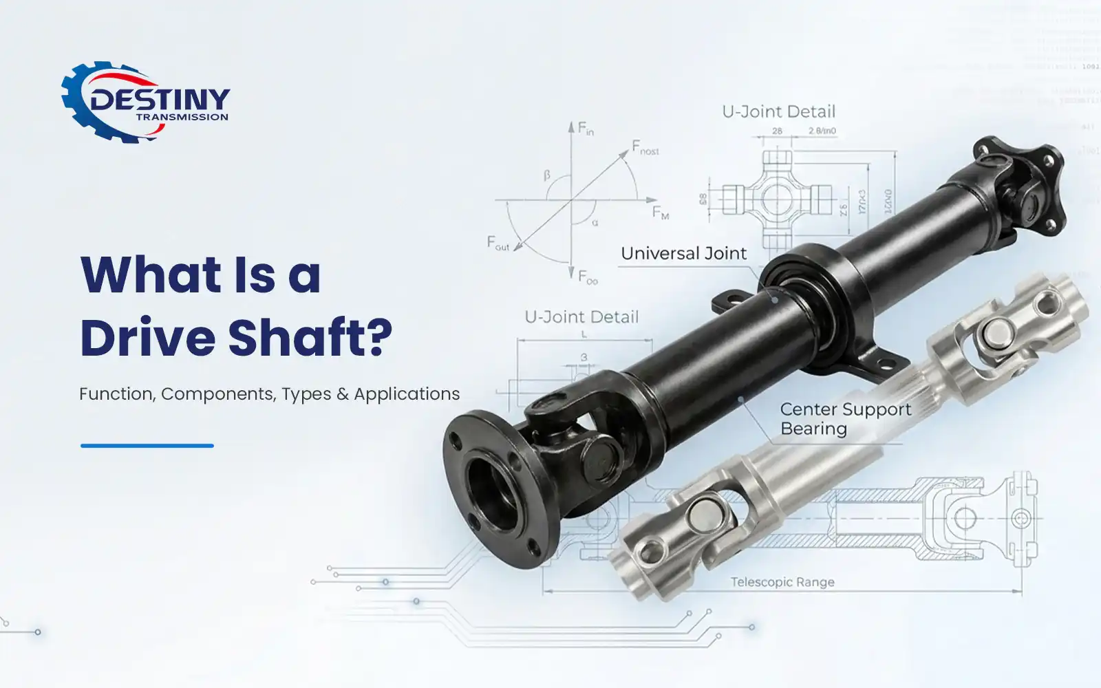
1. What Is a Drive Shaft?
A drive shaft (also referred to as a driveshaft, propeller shaft or prop shaft) is a rotating mechanical component that transmits torque and rotational power between two separated power components. It is designed to automatically compensate for dynamic angular misalignment and axial length changes caused by suspension movement, equipment vibration, thermal expansion or structural displacement during operation.
While widely known for use in automotive drivetrains, drive shafts are also standard in industrial machinery, construction equipment and marine systems for medium-to-long distance power transmission. Note that fixed, rigid shafts sealed inside gearboxes or reducers are not classified as drive shafts, as they do not need to accommodate dynamic angle or length variations.
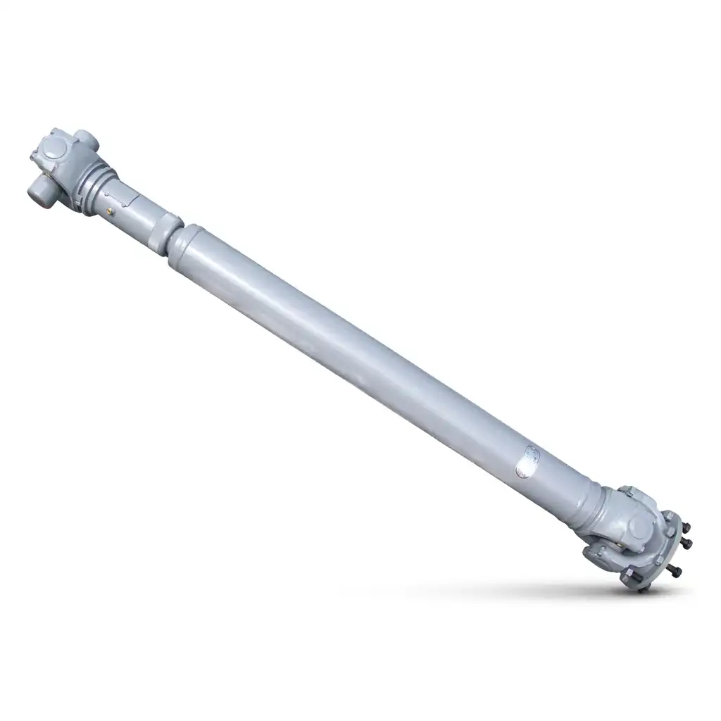
2. How Does a Drive Shaft Work?
The operating principle follows a clear, sequential power flow with built-in adaptive capability:
- Power input – Rotational torque from a transmission, transfer case or gear motor feeds into the drive shaft assembly via a flange or yoke connection.
- Primary angle compensation – The input-side universal joint (or CV joint) adjusts in real time to align with angular changes between the power source and the shaft, preventing binding or power interruption.
- Torque transmission – The hollow shaft tube carries the full torsional load across the distance between input and output points.
- Self-adjusting length compensation – The slip yoke and spline assembly slides axially while continuing to transmit torque, adapting to changes in distance between the two ends caused by movement or thermal effects.
- Secondary angle compensation – The output-side joint compensates for angular offset at the load end, ensuring uniform torque delivery on both sides.
- Power output – Smooth, stable torque is delivered to the driven component, such as a differential, conveyor roller or pump.
- Long-shaft stability support – For extra-long spans, a two-piece design with a center support bearing is used to reduce bending deflection and suppress high-speed resonance.
3. Core Functions of a Drive Shaft
- Torque transmission – Delivers rotational power across a distance between components that cannot be directly connected.
- Dynamic misalignment accommodation – Absorbs angular and axial variations during operation without interrupting power flow.
- Consistent speed delivery – Properly phased joints maintain near-constant output speed, even at operating angles, minimizing vibration and shock loads.
- Long-span power transfer – Enables power transmission over extended distances that would be impractical with a single rigid shaft.
4. Key Components of a Drive Shaft
A drive shaft is an integrated assembly, not a single rigid bar. Its core parts work together to deliver reliable, flexible power transmission:
- Shaft Tube The main load-bearing body, typically a hollow seamless steel tube. Its tubular shape delivers high torsional stiffness with low weight, and raises the critical speed threshold to avoid shaft whip at high RPM.
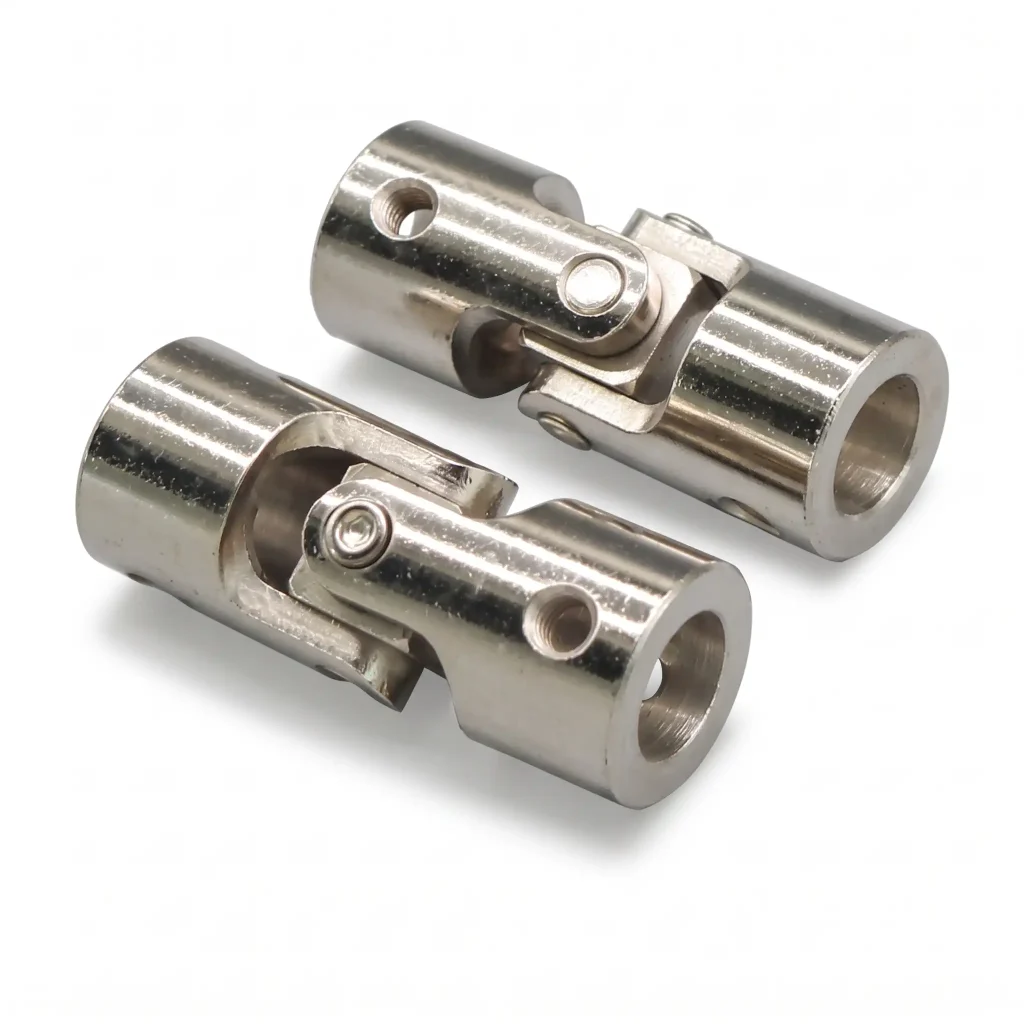
- Universal Joints (U-Joints) Composed of a cross shaft and needle roller bearings, U-joints allow power transfer at operating angles of up to approximately 8 degrees. They are simple, durable and well suited for high-torque, low-angle applications.
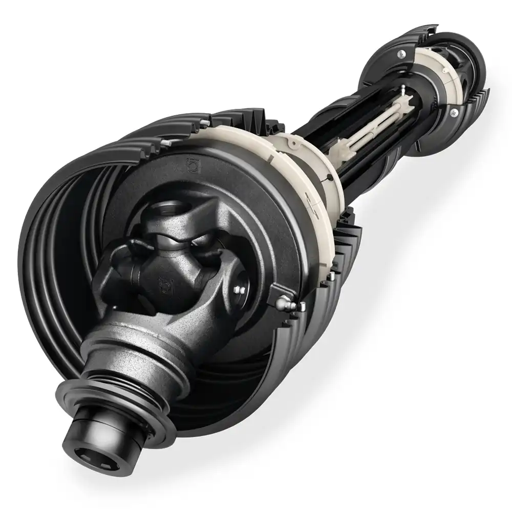
- Constant Velocity (CV) Joints Deliver a true 1:1 input-to-output speed ratio at angles up to approximately 47 degrees. They are used where steeper operating angles are required, and are protected by flexible rubber boots that retain grease and block contamination.
- Slip Yoke & Spline Assembly Consists of mating internal and external splines that slide axially to adjust overall shaft length, while maintaining torque transfer. Wear or inadequate lubrication typically causes clunking during load reversals.
- Yokes (Flange Yoke / End Yoke) Connection components welded or bolted to the shaft ends. They secure the bearing cups of the universal joints and provide the mounting interface to the power source and driven equipment.
- Center Support Bearing Used on two-piece long shafts. It consists of a sealed bearing in a rubber-isolated housing, mounted to a fixed frame to support the midpoint of the shaft, increase critical speed and reduce vibration.
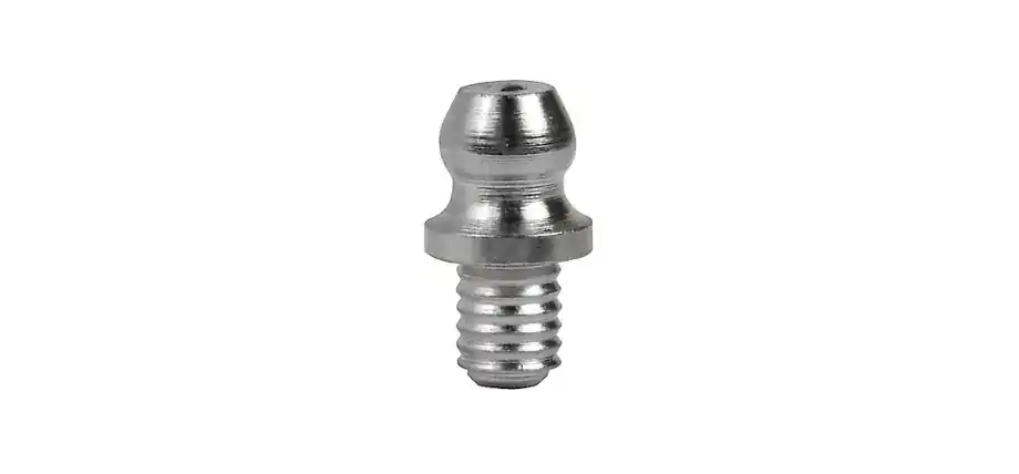
- Seals & Lubrication Fittings Dust seals and grease fittings protect internal bearings from contamination and enable periodic relubrication, extending service life.
5. Common Types of Drive Shafts
Drive shafts are categorized by structure and joint type to match different operating requirements:
- Single-piece drive shaft – A one-piece tubular shaft with joints at each end. Best for short-to-medium spans with moderate operating angles.
- Two-piece drive shaft – Split into two sections with a center support bearing. Designed for long wheelbase vehicles and large-span industrial equipment, to avoid exceeding critical speed limits.
- CV drive shaft – Fitted with constant velocity joints at one or both ends. Used for high-angle applications, front-wheel drive axles and equipment with large suspension travel.
- Telescopic drive shaft – Features an extended spline section for large axial length variation. Common in mobile machinery, lifting equipment and installations with significant thermal expansion.
6. Drive Shaft vs. Gear Shaft: What’s the Difference?
The two are often confused, but serve distinct roles in a power transmission system:
| Comparison Dimension | Drive Shaft | Gear Shaft |
|---|---|---|
| Core function | Transmits torque across a distance, while accommodating dynamic angle and length changes | Transmits torque while integrating gear teeth to change speed, torque or rotation direction |
| Structural feature | Flexible assembly of shaft tube, joints and splines | Rigid shaft body with integrally machined gear teeth |
| Installation requirement | Tolerates angular misalignment and axial float | Requires precise center distance and coaxial alignment |
| Transmission characteristic | Transmits power without changing speed or torque by itself; speed change comes from connected gearing | Built-in gearing directly modifies speed, torque and direction of rotation |
| Mating components | Universal joints, splines, support bearings | Mating gears, precision bearings |
| Typical applications | Vehicle chassis, conveyor systems, long-distance industrial drives | Gear reducers, gearboxes, machine tool spindles |
7. Drive Shaft Materials: A Comparison
Material selection is based on torque requirements, operating speed, weight targets and budget.
| Material | Key Properties | Weight Profile | Typical Applications |
|---|---|---|---|
| Carbon steel (SAE 1020 / 1045) | High torsional strength, low cost, good machinability | Reference weight | Commercial vehicles, general industrial equipment, standard duty applications |
| Alloy steel (42CrMo, 20CrMnTi) | Higher strength, better fatigue resistance, hardenable | Similar to carbon steel | Heavy construction machinery, high-load industrial drives, high-torque vehicles |
| Stainless steel (304 / 316) | Excellent corrosion resistance | Slightly heavier than carbon steel | Food processing, chemical equipment, marine and humid corrosive environments |
| Aluminum alloy (6061-T6) | Lightweight (approx. 35% lighter than steel), high critical speed | 35% lighter | Performance vehicles, light-duty equipment, weight-sensitive applications |
| Carbon fiber composite | Highest stiffness-to-weight ratio, excellent vibration damping | 50–60% lighter | High-performance vehicles, racing, premium lightweight industrial systems |
8. Typical Applications
- Automotive drivetrains – Rear-wheel drive and four-wheel drive passenger cars, trucks and commercial vehicles, connecting the transmission to the differential.
- Industrial machinery – Conveyor systems, packaging lines, pump drives and processing equipment where power must be transferred across spaced components.
- Heavy construction & lifting equipment – Cranes, excavators and hoists, where high torque and reliable performance under dynamic loads are required.
- Marine & agricultural equipment – Boat propulsion systems, farm machinery and off-highway equipment operating in variable terrain and weather conditions.
9. Frequently Asked Questions
Q: What happens when a drive shaft fails?
A: Common symptoms include speed-dependent vibration, clunking during load or direction changes, squeaking at low speeds, and shuddering under acceleration. Severe failure can lead to complete loss of power transmission and secondary damage to connected components.
Q: What is a driving shaft, and how does it relate to a drive shaft?
A: A driving shaft (or driver shaft) is a functional classification, not a distinct component type. It refers to any shaft that supplies input rotational power and drives the rest of the transmission system — the “power input” side of a drivetrain. Its counterpart is a driven shaft, which receives power on the output end.
In everyday usage, the term is sometimes used interchangeably with “drive shaft” when people refer to the full propeller shaft assembly. In strict engineering terms, however, “drive shaft” describes the physical component (the shaft + joints + spline assembly itself), while “driving shaft” describes the role that shaft plays in a given system. A drive shaft can function as a driving shaft when it sits between the power source and the driven component.
Q: What’s the difference between a drive shaft and a propeller shaft?
A: In most contexts the terms are interchangeable. “Propeller shaft” is more commonly used for longitudinal shafts in rear-wheel drive and marine propulsion systems, while “drive shaft” is the broader, more general term.
Q: Can a drive shaft be repaired, or should it be replaced?
A: Minor issues such as worn U-joints, seals or a faulty center bearing can be repaired individually. If the shaft tube is bent, splines are heavily worn, or multiple components are degraded, full assembly replacement is more reliable and cost-effective over the long term.
Q: How do I choose the right drive shaft for my application?
A: Key factors include required torque capacity, operating speed range, maximum working angle, span length, environmental conditions and weight constraints. Custom sizing and material selection are recommended for non-standard industrial applications.
10. Custom Drive Shaft Solutions
We design and manufacture custom drive shafts and gear shafts to your exact specifications, with options for material, joint configuration, length and torque rating to suit automotive, industrial and heavy equipment applications.


