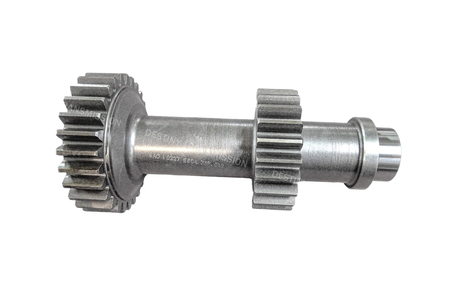
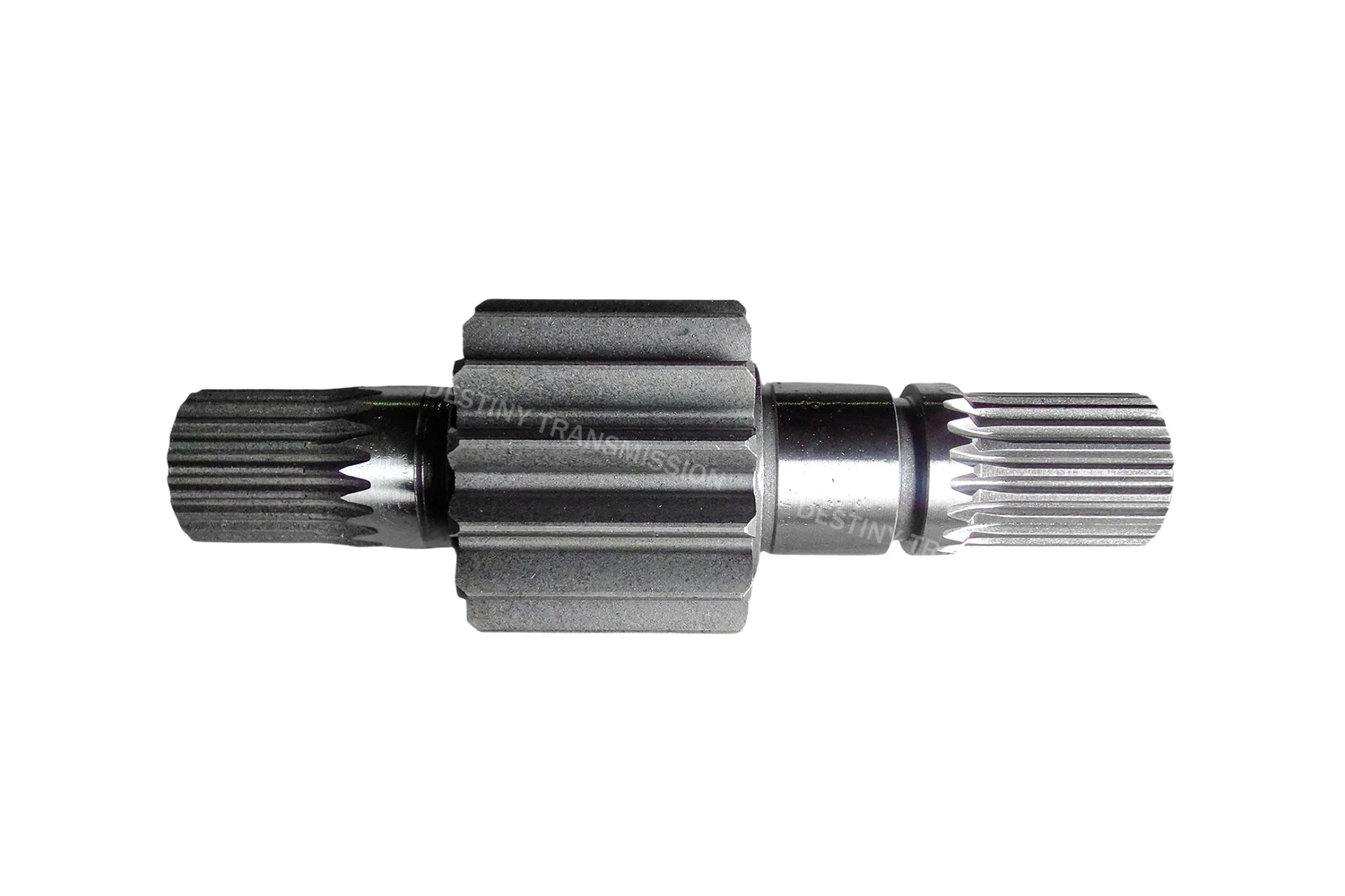
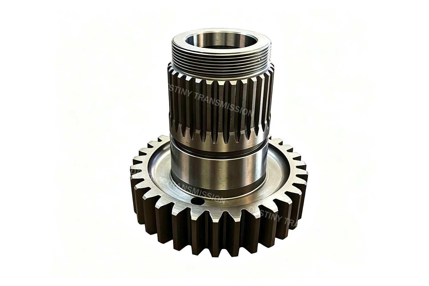
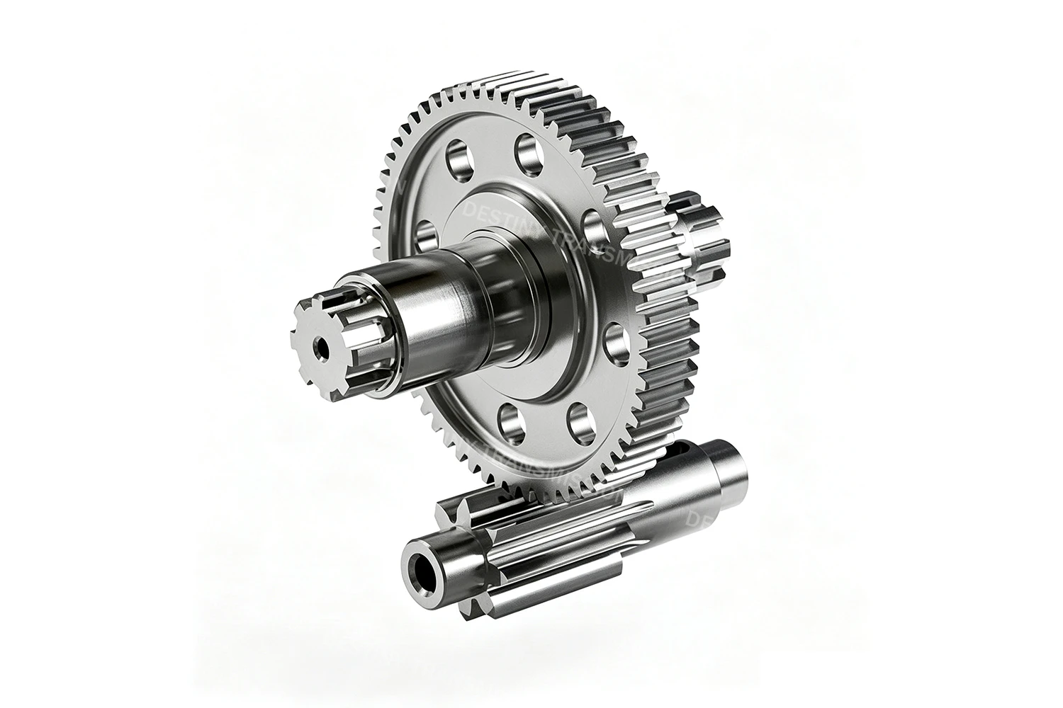
1.What is a Spur Gear Shaft?
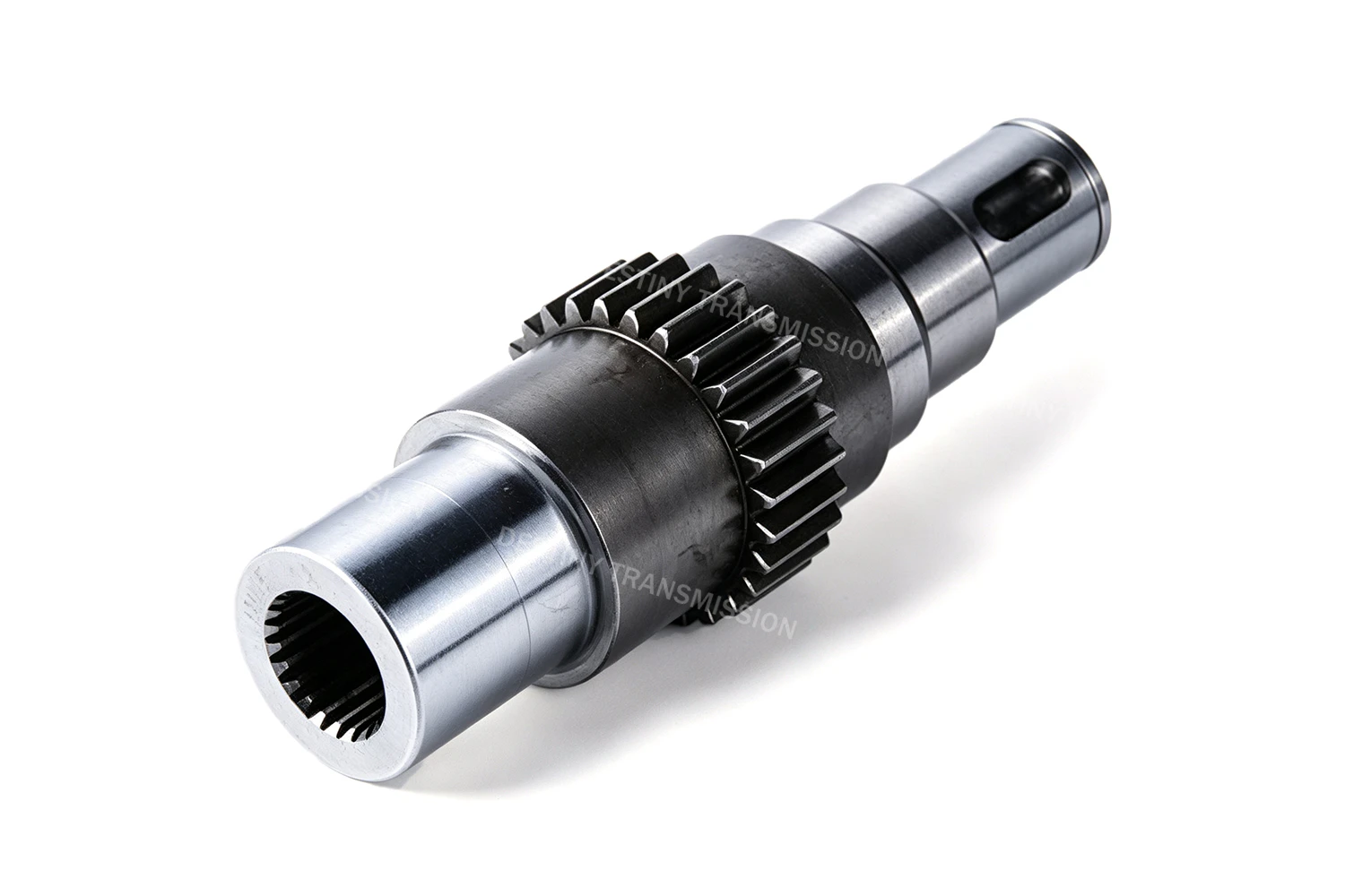
A spur gear shaft, fully designated as a straight-tooth cylindrical gear shaft, is a power transmission component that integrates a spur cylindrical gear and a drive shaft into a single, unified structure. As a widely adopted solution in parallel-shaft power transmission, it stands out for its compact form factor and exceptional transmission rigidity, making it well suited for medium-to-high speed, light-to-medium load applications that demand precise shaft alignment and consistent transmission accuracy.
Its gear teeth are machined directly onto the outer circumference of the shaft body, with the tooth trace running perfectly parallel to the shaft axis in a one-piece, integrally formed construction. Both ends of the shaft are typically machined with support journals, drive keyways, threaded sections and other mounting and locating features. When paired with a mating external gear in external tangential meshing, it transmits power and motion between two parallel shafts, with the input and output shafts rotating in opposite directions.
Compared with an assembly of a separate spur gear and drive shaft, the spur gear shaft eliminates assembly steps such as keyed connections and interference press fits. This completely removes common failure points like gear-to-shaft fit clearance and keyway shear, delivering higher overall transmission rigidity, superior shaft alignment, more stable running accuracy and a reduced installation footprint. The tradeoff is that worn or damaged teeth require full shaft replacement, resulting in higher maintenance costs than split configurations.
Spur gear shafts are widely used in reducer input and output shafts, machine tool feed drives, small gearboxes, motor output ends and other equipment where transmission rigidity and space-efficient layout are priorities.
2.Core Structure and Transmission Characteristics
1.Tooth Profile & Integrated Shaft Design
Spur Internal Gear adopts the industry-standard involute spur tooth profile with a standard 20° pressure angle, with the tooth trace running perfectly parallel to the shaft axis. The gear and shaft stem are integrally formed, eliminating separate assembly steps, delivering superior shaft alignment and transmission rigidity, and featuring a compact overall build that effectively reduces the transmission footprint.
2.Meshing & Transmission Behavior
The full tooth face engages and disengages simultaneously, delivering a constant, accurate transmission ratio with no relative axial sliding between tooth flanks. The one-piece shaft design eliminates keyed connection clearance, resulting in more direct power transfer response. However, it tends to generate meshing impact and noise at high operating speeds, making it better suited for medium- and low-speed conditions.
3.Load & Support Characteristics
This is a defining feature of spur gear shafts: only radial force components are generated during meshing, with no additional axial loads. Mating bearings do not need to account for axial load capacity, simplifying bearing selection and housing support design. The one-piece shaft body provides excellent torsional and bending resistance, and can withstand higher torque and radial loads.
4.Efficiency & Performance Limits
Mechanical transmission efficiency can reach 98% to 99%. With no axial sliding friction on the tooth flanks, power loss is lower than that of equivalently precise helical gear shafts. Its core advantages lie in simple construction, low manufacturing and assembly costs, and stable transmission accuracy. The main limitations are noticeable impact noise at high speeds and limited load contact ratio, making it most suitable for medium- and low-speed transmission scenarios with steady loads.
 +86 184 3796 0706
 info@destinytrans.com