 +86 184 3796 0706
 info@destinytrans.com


Introduction: Why Are Bevel Gears Used in Mechanical Transmission?
In mechanical transmission systems, power does not always need to be transmitted between parallel shafts. When equipment needs to transmit motion and torque between intersecting shafts or change the direction of power transmission, standard cylindrical gears may not be suitable. In such applications, conical gears provide a practical transmission solution.
A bevel gear has teeth formed on a conical surface and is primarily used to transmit power between intersecting shafts. Depending on the tooth form and tooth line design, these components can be manufactured as straight bevel gears, spiral bevel gears, or Zerol bevel gears to meet different requirements for speed, load, noise, and operating performance.
Closely related to this design, hypoid gears feature an offset-axis configuration and are widely used in transmission systems such as automotive differentials.
For custom gear projects, selection should not be based on gear type alone. Factors such as shaft arrangement, transmission ratio, load, rotational speed, accuracy, material, and service conditions should be considered together. This article explains the working principle, main types, common applications, advantages and limitations of these gears, as well as how to select a suitable design based on actual transmission requirements.
1. What Is a Bevel Gear?
A bevel gear has teeth formed on a conical surface and is primarily used to transmit rotational motion and torque between intersecting shafts. Unlike spur and helical gears, which are mainly used for parallel-shaft transmission, this design accommodates power transmission between shafts whose axes intersect at a specified angle. It is commonly used in mechanical systems where the direction of power transmission needs to change.
In a meshing pair, the two shaft axes typically intersect at a defined angle. A 90° shaft angle is a common configuration, although the actual angle depends on the mechanical layout.
Key design parameters include tooth form, number of teeth, dimensions, and shaft angle. Different configurations meet different transmission requirements. Therefore, these components are not simply gears for changing direction, but are designed to suit specific shaft arrangements.
2. How Do Bevel Gears Work?
Bevel gears transmit the rotational motion of the driving gear to the driven gear through meshing tooth surfaces, allowing power to be transmitted between shafts whose axes intersect at a specified angle.
The ratio of the numbers of teeth on the driving and driven gears determines the transmission ratio, which in turn affects the output shaft speed and torque. Therefore, when designing a transmission system, suitable gear parameters should be determined based on the input speed, required output performance, and load conditions.
In addition to the transmission ratio, the actual operating performance of bevel gears is also affected by tooth contact, machining accuracy, and installation conditions. Improper tooth contact or assembly deviations may result in localized load concentration, increased noise, and abnormal wear.
For custom bevel gears, final performance also depends on gear design, manufacturing accuracy, heat treatment, and assembly conditions. These factors should be properly matched to the specific operating speed, load, and working environment.
3. What Are the Main Types of Bevel Gears?
Bevel gears can be classified into different types according to their tooth line and tooth geometry. Different designs affect meshing characteristics, operating smoothness, manufacturing methods, and suitability for different application requirements.
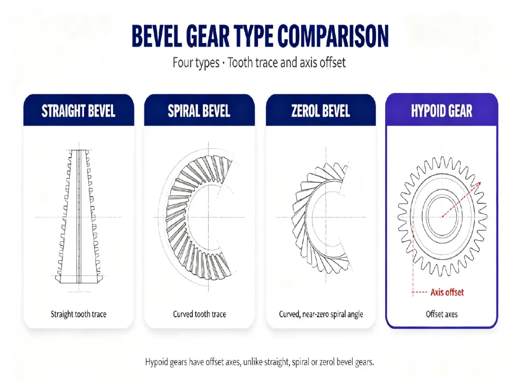
Common bevel gear designs include straight bevel gears, spiral bevel gears, and Zerol bevel gears. Hypoid gears are closely related to bevel gears in terms of structure and application, but because they feature a distinct axis offset rather than intersecting shaft axes, they are generally evaluated as a separate transmission solution.
3.1 Straight Bevel Gear
Straight bevel gears have relatively straight tooth lines extending along the conical surface. Their relatively simple structure and well-established manufacturing processes make them suitable for many general-purpose applications involving angular power transmission.
Compared with more complex tooth geometries, straight bevel gears are easier to manufacture and a good fit when simplicity and cost efficiency are priorities. However, at higher speeds, tooth impact during meshing and operating noise can become significant, so straight bevel gears are generally better suited for low-to-medium-speed applications.
3.2 Spiral Bevel Gear
Spiral bevel gears have tooth lines arranged in a curved or spiral pattern along the conical surface. This tooth geometry allows the teeth to enter engagement progressively and, under appropriate design and manufacturing conditions, generally provides smoother transmission.
Spiral bevel gears are suitable for mechanical systems with higher requirements for speed, load capacity, noise, and operating smoothness and are commonly used in automotive transmissions, industrial gearboxes, and heavy machinery. At the same time, their tooth geometry and manufacturing requirements are more complex, requiring tighter control of tooth flank geometry and contact conditions.
3.3 Zerol Bevel Gear
Zerol gears are a specialized type of spiral bevel gear with a spiral angle close to zero. Their tooth lines resemble those of straight-tooth designs, while their meshing characteristics retain some features of spiral configurations.
As a result, this design can be suitable for applications requiring a balance between structural characteristics, operating smoothness, and transmission performance.
3.4 Hypoid Gears: A Related but Distinct Gear Design
Hypoid gears are closely related to bevel gears but differ in their shaft arrangement. Their defining feature is that the two shaft axes are offset rather than intersecting. This configuration provides greater flexibility in transmission layout and is widely used in applications such as automotive differentials.
These gears generally have more complex tooth geometry and manufacturing requirements, making tooth contact, lubrication, and assembly conditions particularly important. Because the shaft axes are offset, they cannot be designed simply by applying standard parameters for intersecting-axis configurations. The offset distance, tooth contact pattern, and lubrication conditions must be evaluated separately.
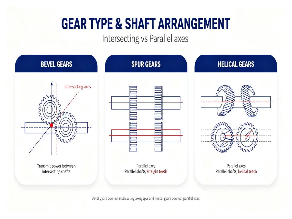
4. What Is the Difference Between Bevel, Spur, and Helical Gears?
Bevel, spur, and helical gears can all be used for power transmission, but they differ significantly in terms of shaft arrangement, tooth geometry, and primary applications.
|
Comparison Item |
Bevel Gear |
Spur Gear |
Helical Gear |
|
Main Shaft Arrangement |
Intersecting shafts |
Parallel shafts |
Parallel shafts |
|
Tooth Geometry |
Teeth formed on a conical surface |
Straight teeth |
Teeth arranged at an angle |
|
Meshing Characteristics |
Depend on the specific tooth geometry |
Relatively direct tooth engagement |
Teeth enter engagement progressively |
|
Operating Characteristics |
Suitable for angular power transmission |
Simple structure and well-established manufacturing process |
Generally provides smoother operation |
|
Typical Applications |
Gearboxes, automotive transmissions, industrial equipment |
General mechanical drives, conveying equipment |
Gearboxes, industrial machinery, automation equipment |
|
Key Selection Factors |
Shaft angle, transmission ratio, load, accuracy |
Number of teeth, module, load, accuracy |
Helix angle, load, speed, noise |
When selecting a gear type, the first consideration should be the relative position of the two shafts. If power needs to be transmitted between intersecting shafts, bevel gears can be evaluated first. If the shafts are parallel, spur and helical gears are typically compared based on the specific transmission requirements.
No single gear type is universally superior. The right choice depends on how well the design matches the actual transmission requirements.
5. What Are the Common Applications of Bevel Gears?
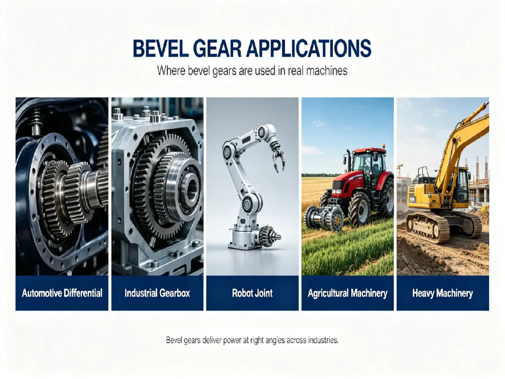
Because bevel gears can transmit power between intersecting shafts, they are commonly used in mechanical systems that need to change the direction of power transmission or optimize shaft arrangement. Their applications range from automotive drivetrains to industrial equipment, automation systems, and heavy machinery.
5.1 Automotive and Transportation Equipment
Bevel gears and related gear designs are widely used in automotive power transmission systems. For mechanisms requiring power transmission between intersecting shafts, the appropriate type of bevel gear can be selected according to the specific design. In automotive differentials, hypoid gears are a particularly typical application. Their offset-axis configuration accommodates the spatial requirements of vehicle drivetrains while meeting the necessary power transmission requirements.
5.2 Industrial Machinery
In industrial machinery, bevel gears are commonly found in gearboxes, transmission systems, machine tools, conveying equipment, and industrial automation equipment. These applications may have different requirements for transmission configuration and installation space, and bevel gears can provide suitable angular transmission solutions based on the mechanical layout.
5.3 Robotics and Automation Equipment
Robots and automation systems often have higher requirements for space utilization, transmission accuracy, and operating smoothness. Bevel gears can be used in space-efficient transmission mechanisms, allowing drive and output components to be arranged along different shaft directions while supporting space-constrained transmission layouts.
5.4 Construction and Heavy Machinery
Construction equipment and heavy machinery typically operate under relatively high loads, and some power transmission mechanisms use bevel gears or related gear designs. For these applications, load-carrying capacity, material selection, heat treatment, and tooth surface quality are important considerations. This is particularly true where impact loads or continuous operation are involved, as the gear strength and durability need to match the actual working environment.
5.5 Agricultural Machinery
Some transmission mechanisms in tractors, harvesting equipment, and other agricultural machinery also use bevel gears to meet specific power transmission and structural requirements. Because agricultural machinery often operates in environments with dust, vibration, and varying loads, material selection, heat treatment, sealing, and durability should be evaluated according to the actual service environment.
Overall, bevel gears are not tied to a specific type of equipment—they are chosen because a transmission system requires a particular shaft arrangement. What determines their suitability is the mechanical layout and working environment.
6. What Are the Advantages and Limitations of Bevel Gears?
The main advantage of these components is their ability to accommodate power transmission between intersecting shafts, providing an alternative to parallel-shaft transmission systems. This makes them particularly suitable for equipment where the direction of power transmission needs to change.
Different tooth geometries also meet different operating requirements. For example, straight designs have a relatively simple structure, while spiral designs generally provide smoother meshing under appropriate design and manufacturing conditions. The choice depends on specific requirements for speed, load, and operating smoothness.
However, these components also have certain limitations. Compared with relatively simple cylindrical gears, they generally involve higher design, manufacturing, and assembly requirements. Complex tooth geometries and high-precision designs require strict control of tooth flank geometry and manufacturing quality.
In addition, they are relatively sensitive to assembly position, shaft alignment, and tooth contact conditions. Improper installation can affect tooth contact and load distribution, potentially resulting in increased noise or abnormal wear. Under high-speed or heavy-duty service conditions, manufacturing and assembly quality become even more important.
Therefore, these components are not a universal solution for all mechanical transmission systems. Their main advantage lies in accommodating specific shaft arrangements and providing reliable angular power transmission, while their manufacturing complexity and assembly requirements must also be considered during selection.
7. How to Choose the Right Bevel Gear?
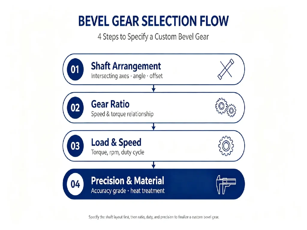
For custom bevel gears, selection should be based on transmission configuration, operating conditions, and manufacturing requirements, rather than starting with a specific gear type.
7.1 Shaft Arrangement and Transmission Ratio
First, confirm the relative position of the two shafts and the shaft angle. If the shaft axes intersect, straight bevel gears, spiral bevel gears, or Zerol bevel gears can be evaluated according to the specific requirements. If the shaft axes are offset, hypoid gears or other suitable designs should be considered.
Next, determine the required transmission ratio. The input and output speeds and torque requirements affect the number of teeth and gear dimensions, which in turn influence the overall layout of the transmission system.
7.2 Load, Speed, and Application Requirements
Once the basic transmission arrangement has been determined, the actual application requirements of the gears should also be evaluated, including rated load, impact load, operating speed, and duty cycle.
For high-speed or heavy-duty equipment, particular attention should be paid to tooth contact, material selection, and heat treatment. If the equipment is sensitive to noise and operating smoothness, tooth geometry, manufacturing quality, and assembly conditions should also be considered.
7.3 Accuracy, Material, and Manufacturing Requirements
Finally, the accuracy grade, material, heat treatment, and tooth surface quality should be defined. These requirements affect the manufacturing process, inspection methods, and overall manufacturing cost.
For custom projects, complete gear drawings and the necessary operating parameters help the manufacturer accurately understand the product requirements and determine the appropriate tooth geometry, manufacturing process, and quality control plan.
Overall, bevel gear selection can be approached in the following order: first determine the transmission configuration, then evaluate the operating conditions, and finally define the manufacturing requirements. There is no fixed solution suitable for every application. A practical design should balance transmission performance, manufacturing feasibility, and actual application requirements.
FAQ: Common Questions About Bevel Gears
Q1: Can Bevel Gears Be Used for High-Speed Transmission?
Yes, but their suitability for high-speed operation depends on the gear design, material, manufacturing accuracy, lubrication, assembly, and actual service conditions. High-speed applications require particular attention to tooth contact, operating smoothness, and noise and vibration control.
Q2: How Should I Choose Between Straight Bevel Gears and Spiral Bevel Gears?
Straight bevel gears have a relatively simple structure and are suitable for many general-purpose transmission applications. Spiral bevel gears provide more gradual tooth engagement and, under appropriate design conditions, are generally better suited to some applications involving higher speeds, heavier loads, or greater requirements for operating smoothness.
Q3: What Is the Difference Between Bevel Gears and Hypoid Gears?
Conventional bevel gears are mainly used for intersecting-shaft transmission, while a defining feature of hypoid gears is that the shaft axes are offset rather than simply intersecting. Although the two designs are closely related, they should be evaluated separately during gear selection.
Q4: How Can I Determine Whether a Project Is Suitable for Bevel Gears?
First, confirm the relative position of the two shafts and the shaft angle, then evaluate factors such as transmission ratio, load, operating speed, installation space, and accuracy requirements. If the system needs to transmit power between intersecting shafts, bevel gears are generally worth considering as a potential solution.
Q5: What Information Is Needed for a Custom Bevel Gear?
It is recommended to provide gear drawings, shaft angle, number of teeth or transmission ratio, main dimensions, material, accuracy requirements, operating speed, load, order quantity, and application conditions. If a complete drawing is unavailable, a sample, photos, or basic specifications can also be provided to help confirm the gear structure and manufacturing requirements.
Conclusion: Choosing the Right Bevel Gear Depends on the Actual Transmission Requirements
The core value of bevel gears lies in meeting power transmission requirements within a specific shaft arrangement. Straight bevel gears, spiral bevel gears, and Zerol bevel gears have different tooth geometries and meshing characteristics, while hypoid gears, with their offset-axis configuration, are suited to specific transmission systems.
There is no universal solution for custom bevel gears. Shaft arrangement and operating conditions determine the most suitable gear design. When requesting custom bevel gears, providing gear drawings, basic dimensions, material, accuracy requirements, order quantity, and application conditions helps the manufacturer evaluate the appropriate gear type, manufacturing process, and production requirements. If a complete drawing is not available, a sample, photos, or basic specifications can serve as a starting point.

Looking for a reliable custom bevel gear manufacturer?
Contact Us to discuss your project requirements and send your drawings, samples, or technical specifications for an initial assessment.


