1. What Is a Spiral Bevel Gear?
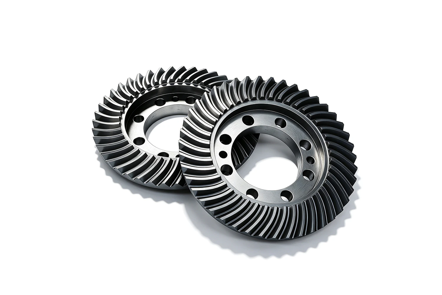
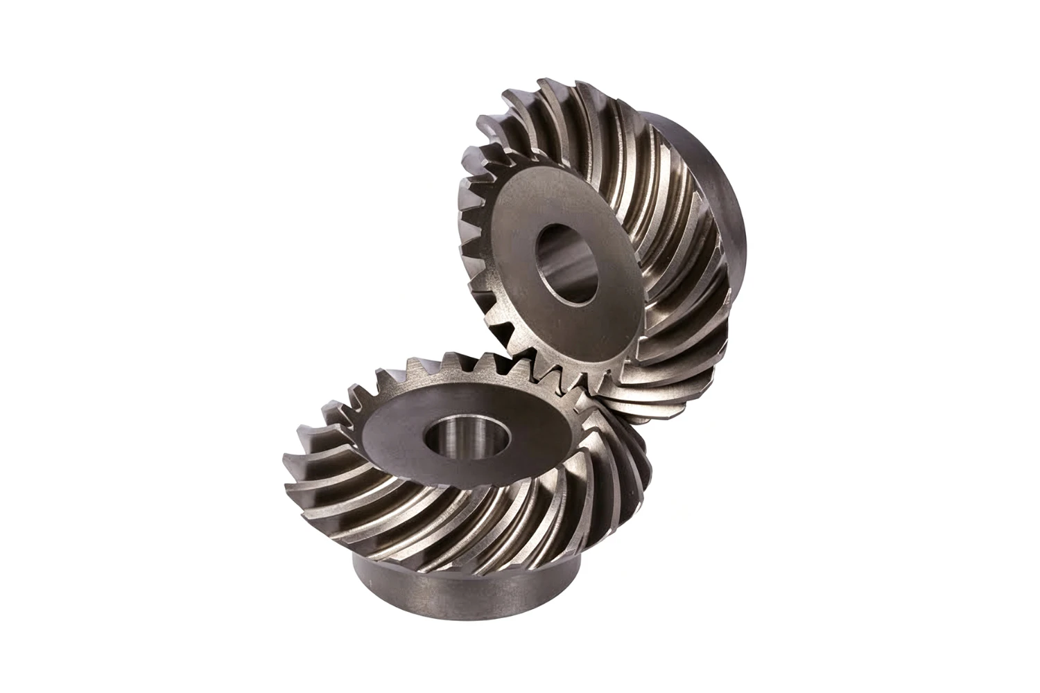
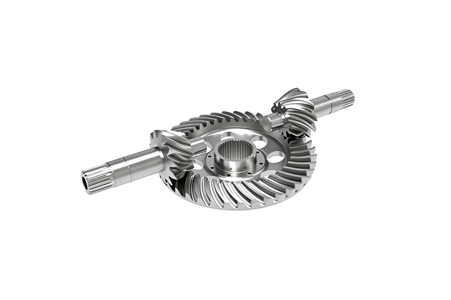
A spiral bevel gear is a precision transmission component for intersecting shafts. It is a key type of bevel gear drive. A matched gear pair transmits motion and torque between the shafts. This changes speed, torque, and the direction of power transmission.
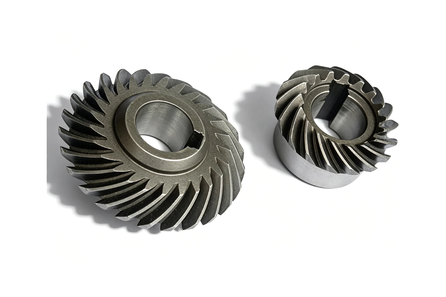
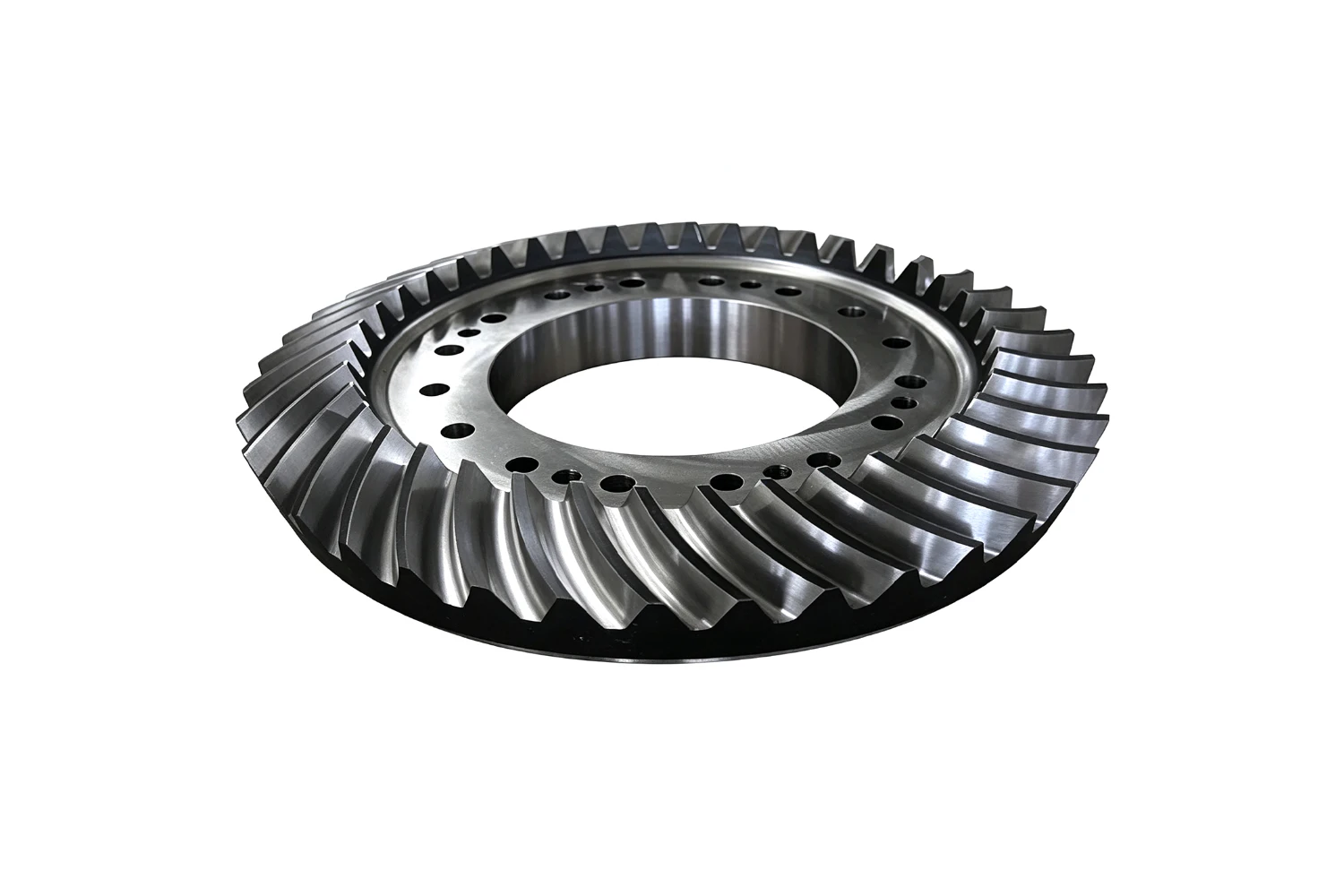
Spiral bevel gears feature curved teeth with a defined spiral angle. Their high contact ratio allows more teeth to engage at the same time. This provides high load capacity, smooth operation, low meshing noise, and good impact resistance. Progressive tooth contact also helps reduce transmission shock and vibration. This makes spiral bevel gears suitable for high-speed and heavy-duty applications.
These gears are widely used in automotive differentials, industrial gear reducers, construction machinery, machine tool spindles, marine drive systems, mining equipment, and agricultural machinery. Common materials include 20CrMnTi, 40Cr, and 20CrMo. Module, tooth count, transmission ratio, accuracy grade, mounting requirements, and operating conditions can be customized.
2. Structure and Transmission Characteristics
2.1 Tooth Profile and Structural Design
Spiral bevel gears use curved tooth lines. They are commonly designed according to Gleason-type or constant-depth tooth systems. Specialized cutting tools form the curved tooth surfaces. These tools help achieve the required meshing characteristics.
The teeth follow a curved path along the cone. The nominal spiral angle is usually measured at the midpoint of the face width. This angle is an important design reference for spiral bevel gear geometry.
Standard tooth systems help maintain consistent meshing accuracy and contact patterns. Precision gears can also be manufactured and lapped as matched pairs. This approach helps optimize tooth contact and transmission performance.
Compared with straight bevel gears, the spiral tooth design generates greater axial forces. The force direction changes with gear rotation and hand. Therefore, bearings and housings must handle axial loads in both directions. This adds structural requirements but also supports smoother transmission and higher load capacity.
2.2 Gear Pair Meshing and Power Transmission
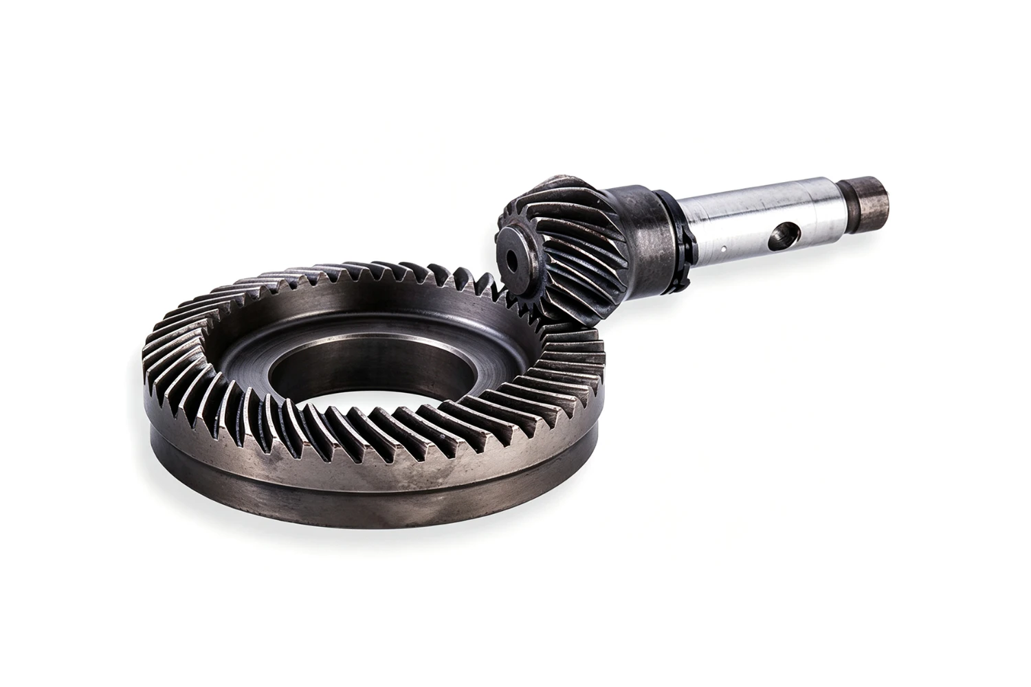
A spiral bevel gear pair is normally used to transmit power between intersecting shafts. A 90° shaft angle is most common. The pinion drives the mating gear to convert speed and torque while changing the direction of power transmission.
The teeth enter and leave contact gradually along the face width. More teeth can share the load at the same time. This gives the spiral bevel gear drive a higher contact ratio than a straight bevel gear drive. It also reduces transmission impact and improves load distribution.
This meshing characteristic allows the gear pair to operate smoothly under high torque and high reduction requirements. Multiple spiral bevel gear pairs can also be combined for power splitting, direction changes, and other transmission layouts.
2.3 Transmission Efficiency and Operating Characteristics
A properly designed spiral bevel gear drive can achieve high mechanical efficiency. Correct installation and suitable lubrication are also important for stable operation.
The progressive tooth engagement helps reduce vibration and meshing noise. As a result, spiral bevel gears generally provide smoother operation at higher speeds than straight bevel gears.
Common manufacturing processes include gear milling, gear grinding, and matched lapping. These processes help control transmission accuracy and tooth contact. Heat treatments such as carburizing and hardening or quenching and tempering can improve tooth surface hardness, wear resistance, and contact fatigue strength.
2.4 Performance and Application Suitability
The main advantages of spiral bevel gears include a high contact ratio, strong load capacity, smooth operation, and relatively low noise. They are suitable for high-speed and heavy-duty transmission systems where stable power transfer is important.
Compared with straight bevel gears, however, spiral bevel gears require more complex machining and higher manufacturing costs. Their greater axial forces also place higher demands on bearings, housings, and other supporting structures.
Materials for spiral bevel gear transmission systems, such as 20CrMnTi, 40Cr, and 20CrMo, can be selected according to operating conditions. Module, tooth count, transmission ratio, spiral angle, accuracy grade, and heat treatment can be customized for different loads, speeds, and installation spaces.
This makes the spiral bevel gear suitable for applications ranging from light-duty precision drives to heavy-duty industrial transmission systems.
 +86 184 3796 0706
 info@destinytrans.com