 +86 184 3796 0706
 info@destinytrans.com


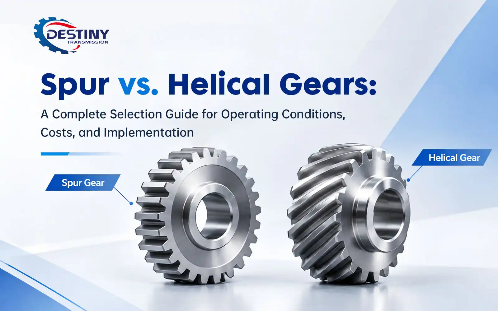
In industrial transmission system design, selecting the right tooth profile is often reduced to a simple parameter matching exercise, while the knock-on effects of this choice on system noise, service life, and total cost of ownership are easily overlooked. Many projects run into issues like excessive vibration, shortened bearing life, and unexpected operating cost overruns after commissioning — and more often than not, the root cause is a mismatch between the tooth profile selected and the actual operating conditions.
When evaluating helical vs spur gear solutions, it is critical to look beyond basic dimensional parameters. This guide breaks down the full selection logic for both profiles, covering design fundamentals, performance tradeoffs, total cost analysis, application matching, and procurement best practices. It is built to help design engineers, maintenance teams, and procurement professionals identify the optimal solution for their specific requirements.
1. Fundamental Design Differences: Working Principles of the Two Tooth Profiles
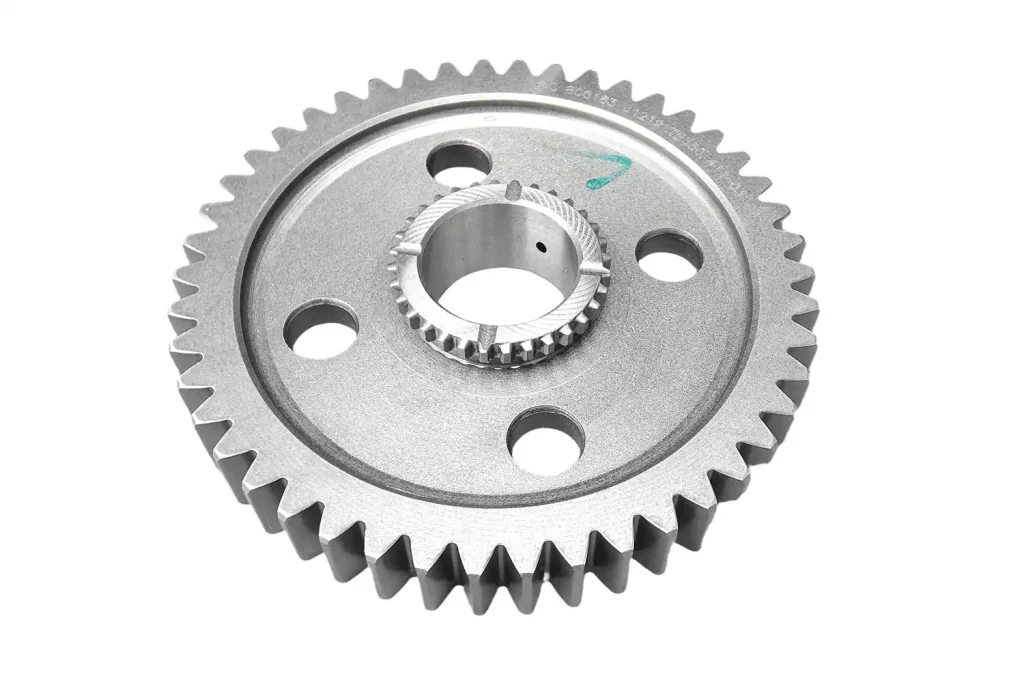
Spur Gears: Instantaneous Full-Face Meshing
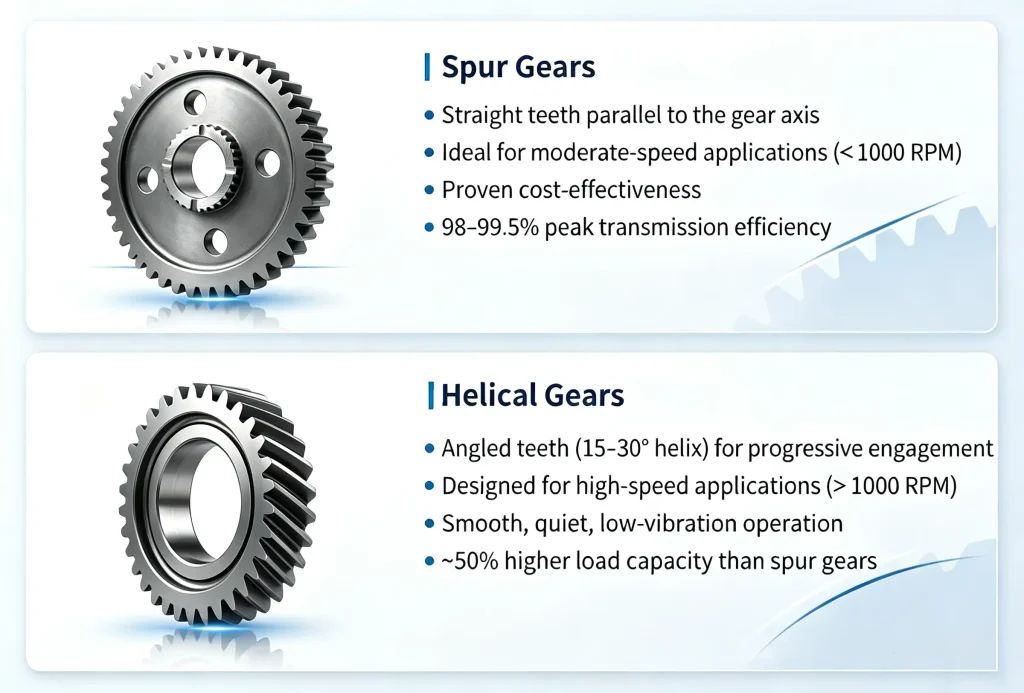
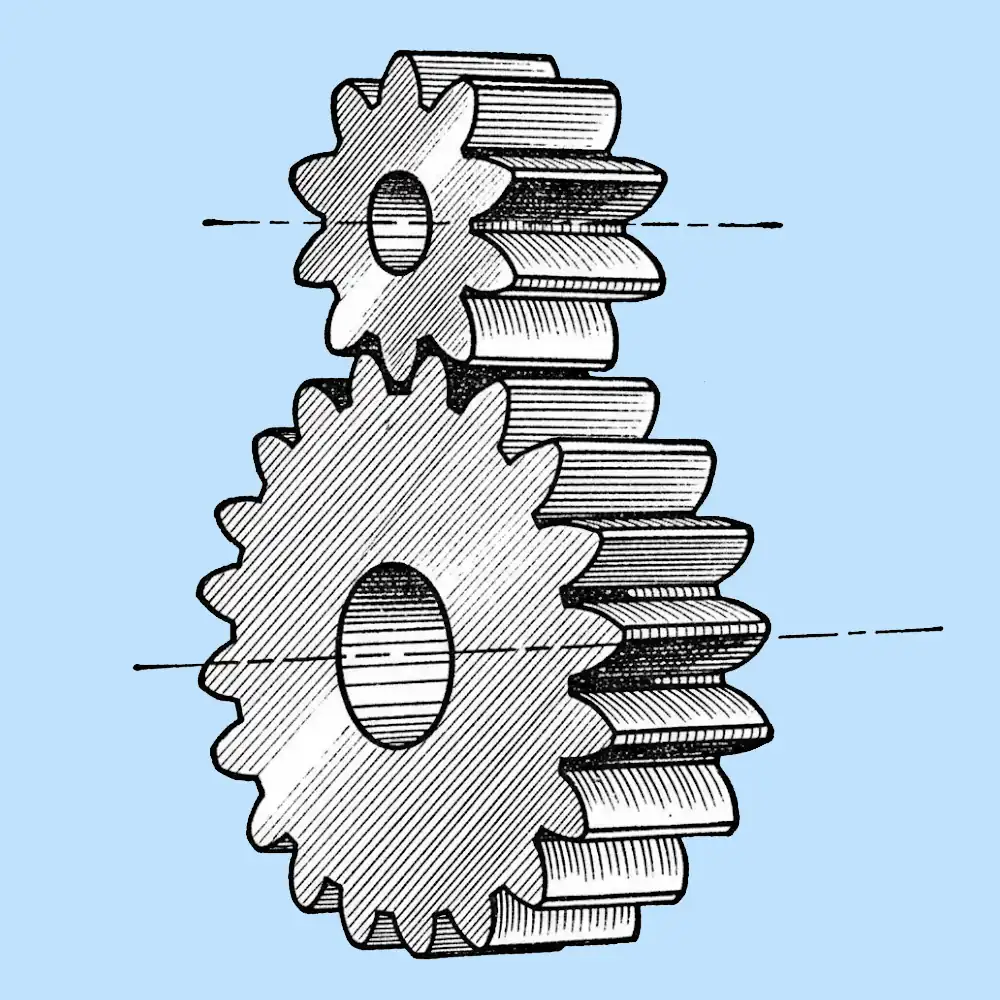
Spur gears, also called straight cut gears, feature teeth cut perfectly parallel to the gear axis — the simplest form of cylindrical gearing. During meshing, the entire face width of each tooth makes contact and disengages at the same time, creating an instantaneous full-face engagement pattern.
This engagement behavior yields a contact ratio typically between 1.2 and 1.6, meaning a relatively small number of teeth carry the load at any given moment. At higher rotational speeds, this generates impact stress and the characteristic whine of straight cut gearing. That said, since contact is nearly pure rolling with minimal sliding friction, mechanical losses are exceptionally low.
Helical Gears: Progressive, Gradual Meshing
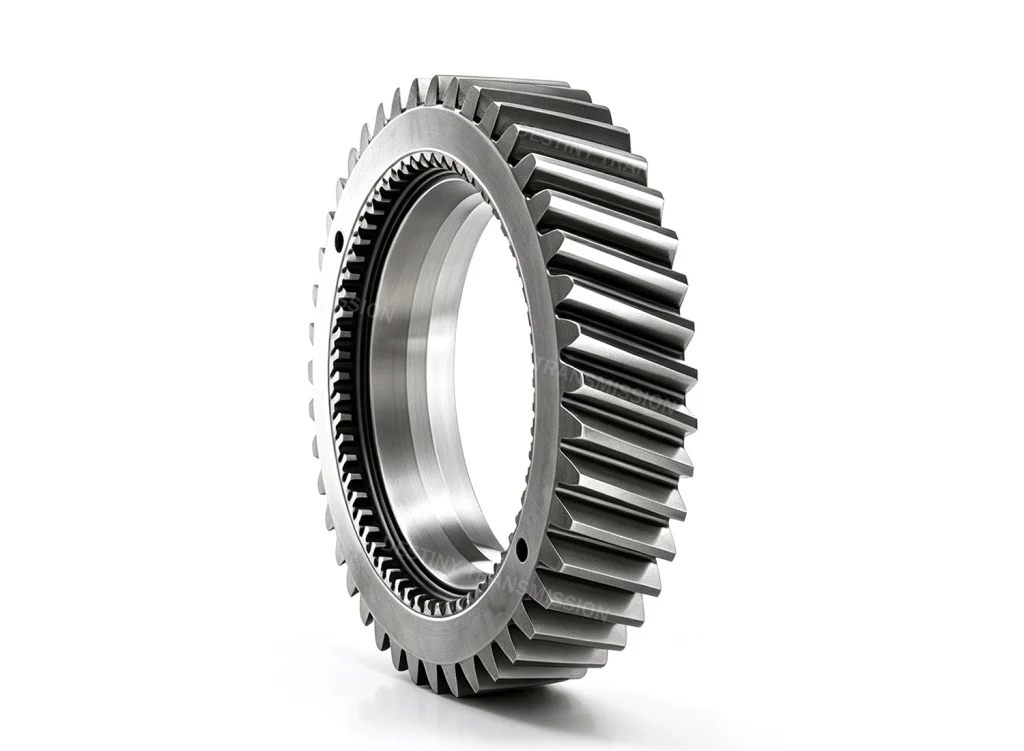
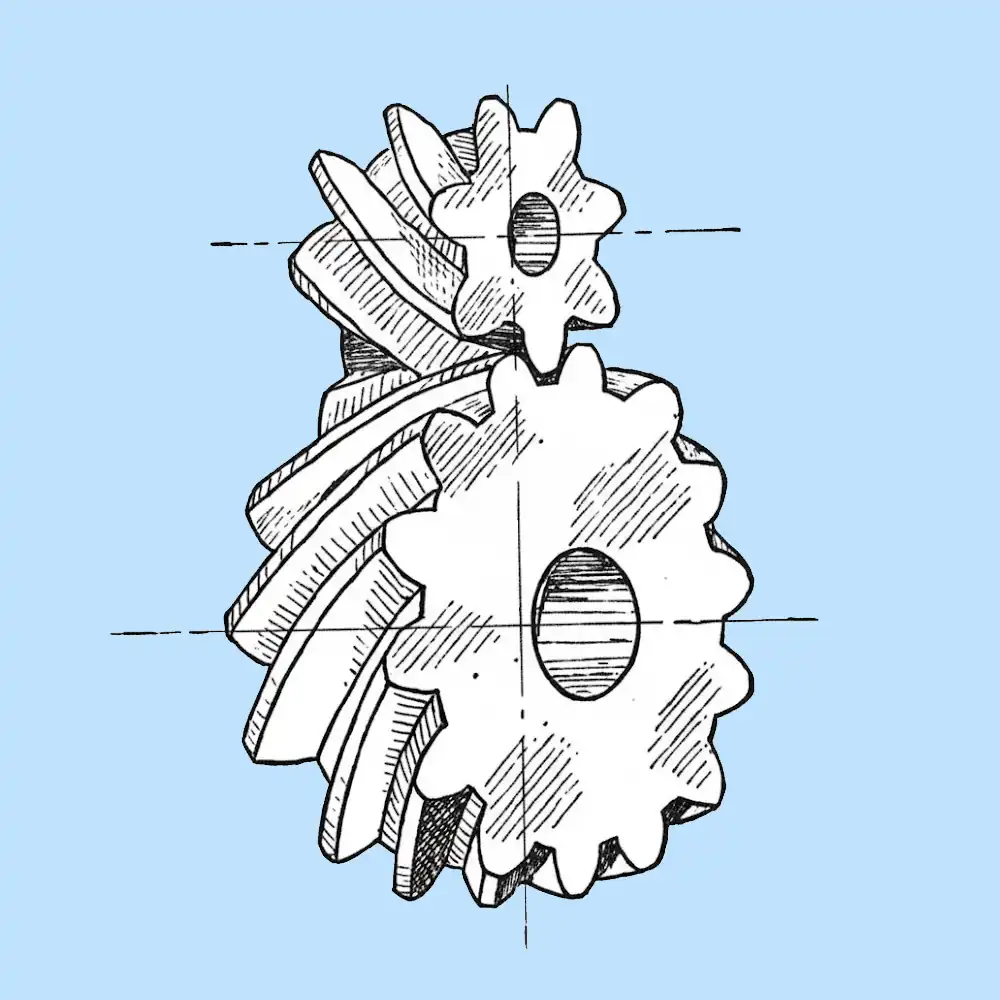
Helical gears have teeth cut at a helix angle of 15° to 30° relative to the axis, forming a spiral pattern around the gear body. During meshing, contact points move gradually across the tooth face from one end to the other, delivering a smooth, progressive engagement.
Under typical operating conditions, 2 to 3 teeth remain in mesh simultaneously, pushing the contact ratio above 2.0. Load is distributed across multiple teeth, reducing impact and improving running smoothness. The tradeoff is that the angled teeth generate axial thrust loads that must be absorbed by the rest of the drive train.
2. Full-Spectrum Performance Comparison: Defining the Practical Limits of Each Profile
The performance gap between helical gear vs spur gear designs becomes most apparent when evaluating load capacity, noise behavior, and mechanical efficiency under real-world operating conditions.
Load Capacity and Shock Resistance
Thanks to their higher contact ratio and multi-tooth load sharing, helical gears deliver roughly 50% higher load capacity than equivalently sized spur gears of the same material. They also absorb variable and shock loads far more effectively, making them well suited for heavy-duty applications with fluctuating duty cycles.
Spur gears, by contrast, concentrate load on fewer teeth. This makes them more susceptible to impact stress and fatigue damage under heavy or fluctuating loads. Their load capacity is considered standard, and fully adequate for many steady-state, medium-duty applications.
Running Smoothness and Noise
The instantaneous engagement of spur gears produces noticeable vibration and meshing noise once speeds exceed 1,000 RPM, typically reaching 85–95 dB or more. This makes them difficult to deploy in noise-sensitive environments.
Helical gears eliminate the hard tooth impact through progressive engagement. Even at speeds above 3,000 RPM, they maintain smooth, quiet operation with noise levels typically between 65 and 78 dB — making them the default choice for low-noise requirements.
Shaft Arrangement and Bearing Compatibility
Spur gears generate only radial loads, so they can be used with simple, low-cost radial bearings and simplified bearing housing designs. Assembly and alignment requirements are also less demanding.
Helical gears generate significant axial thrust. This requires thrust-rated bearings such as angular contact ball bearings or tapered roller bearings, as well as stiffer, more robust bearing housings and higher alignment precision during assembly.
In terms of shaft arrangement flexibility: spur gears are only suitable for parallel shaft drives. Helical gearing can be configured for both parallel shafts and crossed shafts at angles from 0° to 90°, offering greater layout flexibility where space is constrained.
Mechanical Efficiency
Spur gears achieve 98–99.5% efficiency thanks to near-pure rolling contact with very little sliding friction, resulting in extremely low energy loss.
Helical gears typically run at 96–98% efficiency, as the angled tooth contact introduces a small amount of axial sliding friction. While the efficiency difference may seem minor on a single machine, it compounds significantly over continuous long-term operation.
3. Total Cost of Ownership: Look Beyond the Initial Gear Price
Many selection decisions focus only on the purchase price of the gear itself, ignoring the hidden costs of system integration and long-term operation. For teams weighing helical vs straight cut gears, the difference in total cost of ownership is far larger than the difference in unit price alone.
Manufacturing Cost
- Spur gears are produced with simple 2-axis machining processes. Production is fast, inspection is straightforward, and base manufacturing costs are lower.
- Helical gears require 3-axis machining with specialized hobbing tools tailored to the helix angle. Production and setup take longer, and unit pricing is typically 30–40% higher than comparable spur gears.
System Integration Cost
- Spur gears work with standard radial bearings and simple housing designs, keeping integration costs low.
- Helical gears require thrust bearings, reinforced housings, and additional axial space. Bearing costs alone can rise by 30–50%, and overall axial space requirements increase by 15–25%, driving up total system cost.
Operating and Maintenance Cost
In energy terms, for a 50 kW industrial motor running 8 hours per day, 300 days per year, a 1.5% efficiency gap adds roughly $200–280 in extra electricity costs per year. Over a 10-year service life, that accumulates to $2,000–2,800 in additional energy expense.
On the maintenance side, spur gear systems are simple, use widely available spare parts, and are quick to service. Helical systems involve more components — bearings, housings, and precision alignment requirements — increasing both maintenance complexity and cost.
4. Application-Based Selection Framework: Three Steps to the Optimal Profile
There is no universally “better” gear type. The right choice depends on matching the profile to the operating requirements and cost constraints. Use this three-step process to quickly narrow down the best option.
Step 1: Evaluate speed and noise requirements
- Operating speed < 1,000 RPM with no strict noise limits → prioritize spur gears
- Operating speed > 1,000 RPM or explicit low-noise requirements (< 75 dB) → prioritize helical gears
Step 2: Evaluate load and duty cycle characteristics
- Steady, moderate loads with minimal shock → spur gears are sufficient
- Heavy loads, variable loads, or high impact conditions → helical gears are more suitable
Step 3: Evaluate space and cost constraints
- Tight axial space, budget-sensitive projects, or priority on low upfront cost → spur gears
- Available space, and willingness to invest in higher performance and longer service life → helical gears
Typical Application Reference
| Gear Type | Primary Applications |
|---|---|
| Spur Gears | Material handling conveyors, low-speed agricultural machinery, general-purpose gearboxes, packaging equipment, small appliance transmissions |
| Helical Gears | Automotive transmissions, CNC machine tools, industrial robots, elevators and escalators, HVAC systems, medical equipment, high-speed conveyors |
Quick Selection Checklist
| Evaluation Criterion | Better Fit for Spur Gears | Better Fit for Helical Gears |
|---|---|---|
| Cost Sensitivity | High; prioritize upfront cost | Low; acceptable higher investment |
| Operating Speed | ≤ 1,000 RPM | > 1,000 RPM |
| Noise Requirement | No strict limit | Low-noise operation required |
| Load Profile | Steady, medium duty | Heavy / shock load |
| Axial Space | Tight / constrained | Sufficient space available |
| Maintenance Priority | Simple, easy maintenance | Acceptable more complex design |
Rule of thumb: if one profile matches four or more criteria, it is likely the optimal choice for your application.
5. Real-World Industry Case Studies
The value of proper profile selection lies in matching the gear to the application, not chasing the highest possible specifications. These three industry examples illustrate how the right — or wrong — choice impacts performance and cost.
Case 1: Low-Speed Heavy-Duty Ore Conveyor – Spur Gears Deliver Cost-Effective, Long-Life Operation
Background: A building materials company needed a main drive drum for an ore conveyor line running at 420 RPM under steady load, 24/7 continuous operation. The project had strict budget controls, prioritizing both low upfront cost and long-term reliability.
Selection Process: An initial concept considered helical gears, but a full operating assessment showed that at speeds well below 1,000 RPM with steady load, the noise and load advantages of helical gearing would never be realized. Instead, the design would incur unnecessary additional costs for thrust bearings and reinforced housings. The final selection used 45 steel quenched & tempered spur gears with deep groove ball bearings and simple cast steel housings.
Results: Transmission efficiency stabilized above 98.5%. Gear unit purchase cost was 32% lower than the helical gear alternative. Bearing service intervals reached 24 months, and the system ran for 5 consecutive years without tooth fatigue, breakage, or other failures — fully meeting operational requirements.
Key Takeaway: For low-speed, steady-load, cost-sensitive projects, spur gears are the more economical and reliable choice.
Case 2: High-Precision CNC Machining Center – Helical Gears Meet High-Speed, Low-Noise, High-Rigidity Requirements
Background: A vertical CNC machining center spindle gearbox with a maximum speed of 3,500 RPM required idle noise ≤ 70 dB, plus high rigidity and shock resistance under heavy cutting loads with large fluctuations.
Selection Process: The first prototype used a spur gear design, which reached 89 dB during high-speed idle operation, exhibited noticeable vibration during heavy cutting, and suffered rapid tooth wear — failing to meet precision requirements. The optimized design switched to alloy steel helical gears with a 20° helix angle, paired with matched angular contact ball bearings, reinforced housing rigidity, and tighter assembly tolerances.
Results: High-speed idle noise dropped to 67 dB. Operation was smooth and shock-free under heavy cutting conditions. Load capacity increased by 45%, tool life extended by 18%, and long-term accuracy stability improved significantly — meeting the performance requirements of a high-end machine tool.
Key Takeaway: For high-speed, low-noise, variable-load applications, the performance advantages of helical gears translate directly into better equipment performance.
Case 3: Cautionary Tale – Misaligned Selection Drives Up Cost and Reduces Reliability
Background: A small feed machinery manufacturer upgraded the transmission on a feed mixer from spur gears to helical gears, despite the machine operating at only 360 RPM under steady, low-impact load.
Issues: At such low speeds, the smooth meshing benefits of helical gears were completely undetectable. Instead, the upgrade increased drive system cost by 38% due to thrust bearings and reinforced housings, eroding the machine’s profit margin. Additionally, because the factory did not upgrade assembly precision accordingly, the field saw increased issues like axial end play and bearing overheating, driving a 27% year-over-year increase in warranty repairs.
Key Takeaway: Specifying a “higher performance” profile without aligning it to actual operating conditions does not add value — it wastes cost and introduces unnecessary reliability risks.
6. Custom Procurement Best Practices: Requirements and Quality Control
For custom gear projects, clear, complete requirement documentation is critical to ensuring on-time delivery and consistent quality. Organize your request into three categories:
1. Basic Geometric Parameters
- Gear type (spur / helical), module / diametral pitch, pressure angle, number of teeth
- For helical gears: helix angle and hand of helix
- Outside diameter, bore diameter, face width, and connection features such as keyways, splines, hubs, and mounting holes
- Mating gear parameters or assembly relationship details
2. Operating and Technical Requirements
- Load, torque, speed range, duty cycle, rotation direction
- Material grade requirements, heat treatment and hardness specifications
- Surface treatment, corrosion protection, and operating environment (temperature, contaminants, etc.)
- Accuracy grade, noise targets, axial load limits, and other special requirements
3. Delivery and Quality Documentation Requirements
- Order quantity, prototype / production status, and required lead time
- Required quality documentation and certifications
Quality documentation requirements vary widely by project, so it is recommended to define them at the RFQ stage to avoid additional coordination costs later. Common deliverables include material certificates, dimensional inspection reports, gear inspection reports, heat treatment / hardness reports, surface treatment reports, first article inspection (FAI), PPAP documentation, certificates of conformity (COC), and batch traceability records.
For high-precision applications, machining up to DIN Grade 4 accuracy is available, subject to project-specific review.
7. Final Summary
There is no universal winner in the helical vs spur gear debate — the best choice is always the one that matches your operating conditions.
Spur gears excel with their simple design, low cost, and high mechanical efficiency, making them the cost-effective choice for medium- and low-speed steady-state applications.
Helical gears stand out for smooth, quiet operation and higher load capacity, making them ideal for high-speed, heavy-duty applications where performance and refinement are priorities.
When making your selection, always prioritize real operating requirements over chasing higher performance specifications — this avoids unnecessary cost and over-engineering.
As a precision transmission component manufacturer, we offer full custom manufacturing for both spur and helical gears, covering the entire process from blank preparation and precision machining to heat treatment and final inspection. If you have selection questions or a specific project, send us your drawings and operating conditions, and we can provide free drawing review, selection recommendations, and process feasibility assessment.


