1. What is an external helical gear?
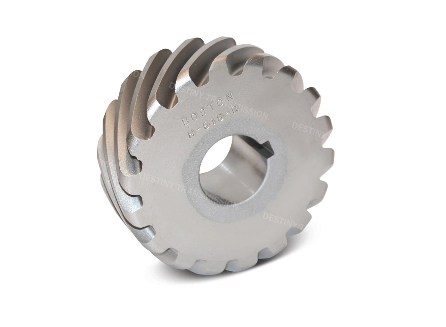
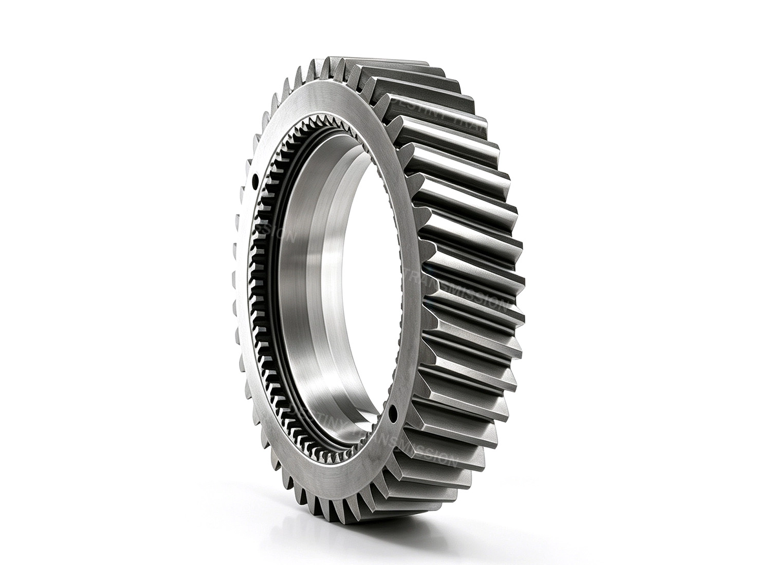
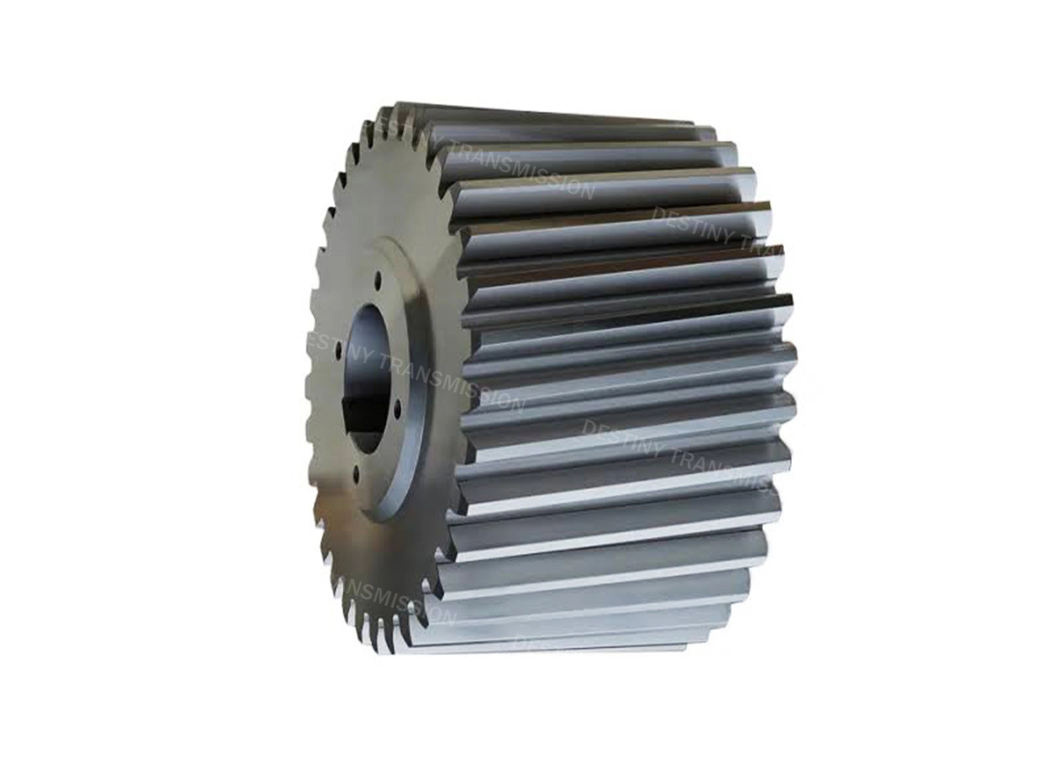
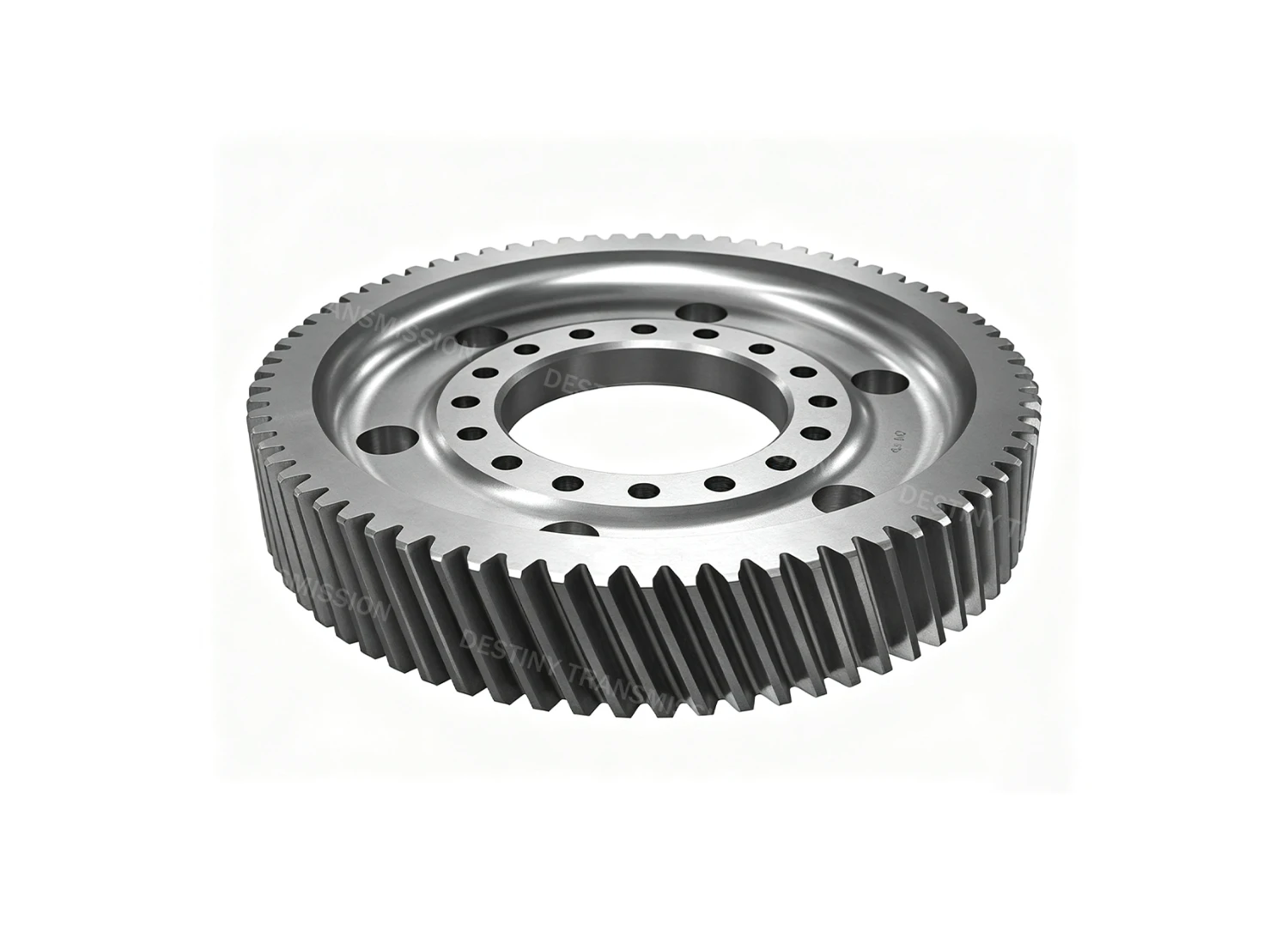
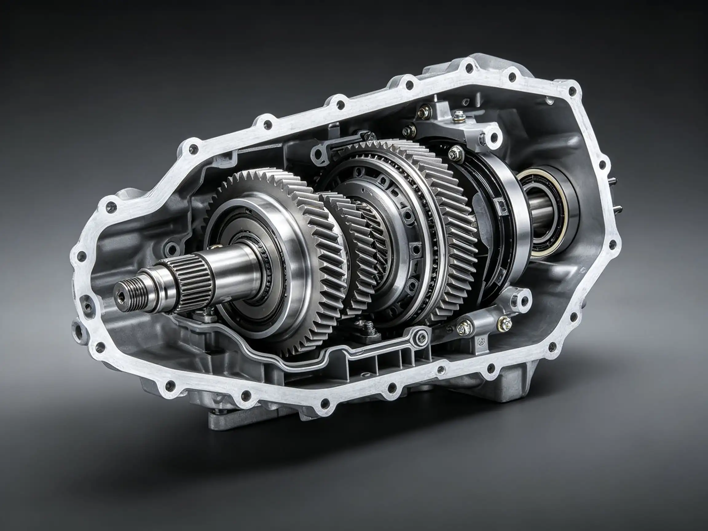
The full name of the external helical gear is external helical cylindrical gear. It is a widely applied category of cylindrical gear in the field of parallel shaft transmission, and also the mainstream selection for medium-high speed and heavy-duty industrial transmission scenarios.
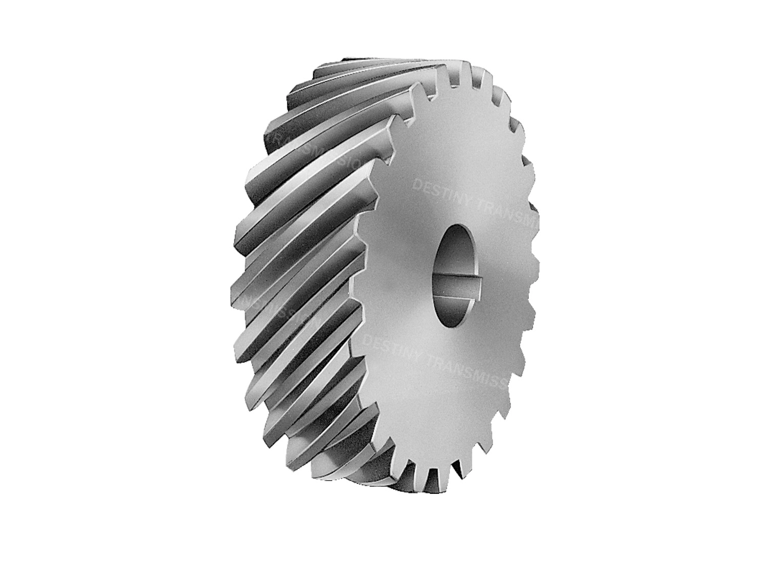
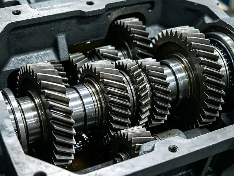
Its gear teeth are evenly distributed on the outer circumferential surface of the cylinder, and the direction of the tooth trace forms a certain helical included angle with the gear axis (namely the helix angle). When assembled in pairs, it meshes tangentially with another external helical gear on the outside, and can smoothly transmit power and motion between two parallel shafts. After meshing, the input shaft and the output shaft rotate in opposite directions.
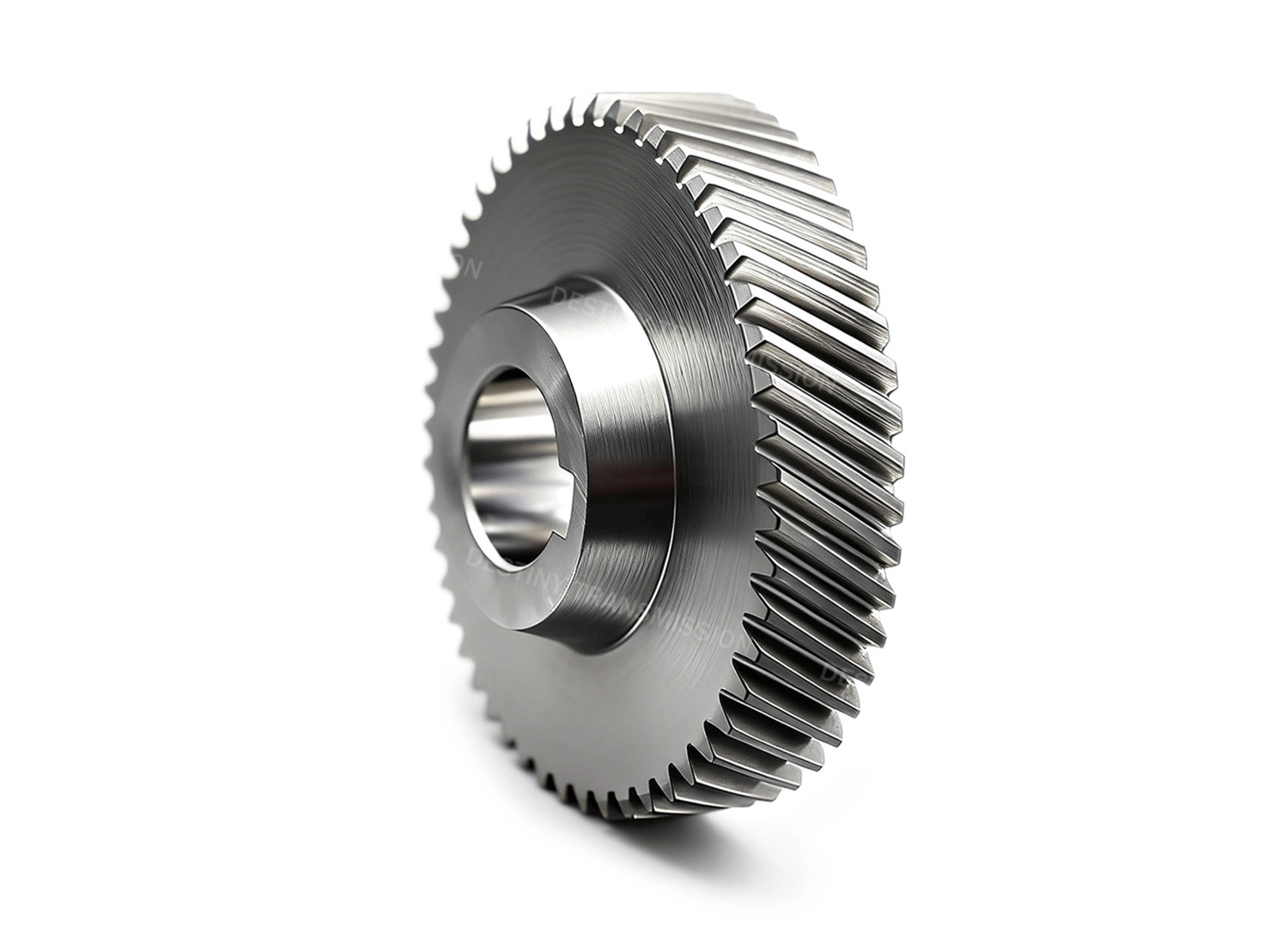
Compared with external spur gears, the teeth of external helical gears engage and disengage progressively, with a higher contact ratio. Therefore, they feature smoother transmission, lower meshing noise and stronger load-carrying capacity, and are often used in equipment such as gear reducers, machine tool spindles and high-speed gearboxes that have requirements for transmission smoothness and noise control. The disadvantage is that axial thrust will be generated during meshing, which requires matching thrust bearings, and the structural design and manufacturing cost are slightly higher than those of external spur gears.
2. Core Structure and Transmission Characteristics
1. Tooth Profile and Helix Angle Design
The tooth profile adopts the industry-standard involute tooth form with a standard pressure angle of 20°. The core difference from spur gears is that the teeth are distributed along the helical path, and the tooth trace forms a fixed included angle with the gear axis, namely the helix angle, which generally ranges from 8° to 20° in the industry. The larger the helix angle, the higher the meshing contact ratio, but the greater the axial thrust generated during operation.
2. Meshing and Transmission Characteristics
The teeth engage and disengage progressively. More teeth remain in mesh simultaneously compared with external spur gears, delivering a higher contact ratio. During transmission, impact is minimal and meshing noise is low; running stability is significantly superior to spur gears, with stronger load-carrying capacity, making it more suitable for high-speed and heavy-duty transmission conditions.
3. Axial Thrust Characteristics
This is the most distinctive structural feature of external helical gears: an axial force component is generated along the axis direction during meshing. For this reason, matching bearings must be selected from types capable of withstanding axial loads, and the housing structure must also be reinforced accordingly. In engineering practice, symmetrically mounted herringbone gear sets are often used to counteract bidirectional axial thrust.
4. Efficiency and Performance Limits
The mechanical transmission efficiency is approximately 97% to 98%. Due to axial sliding on tooth flanks and additional friction from bearings, it is slightly lower than that of external spur gears of the same precision grade. Its overall advantages are concentrated in smooth operation and low noise under high-speed and heavy-duty conditions, while its limitations lie in higher machining and assembly complexity, as well as higher manufacturing costs than external spur gears.
 +86 184 3796 0706
 info@destinytrans.com