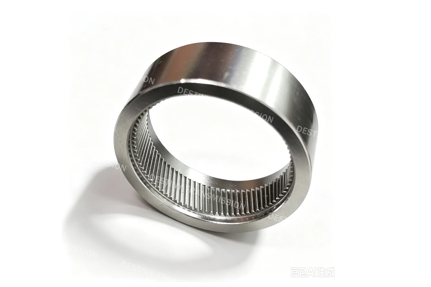
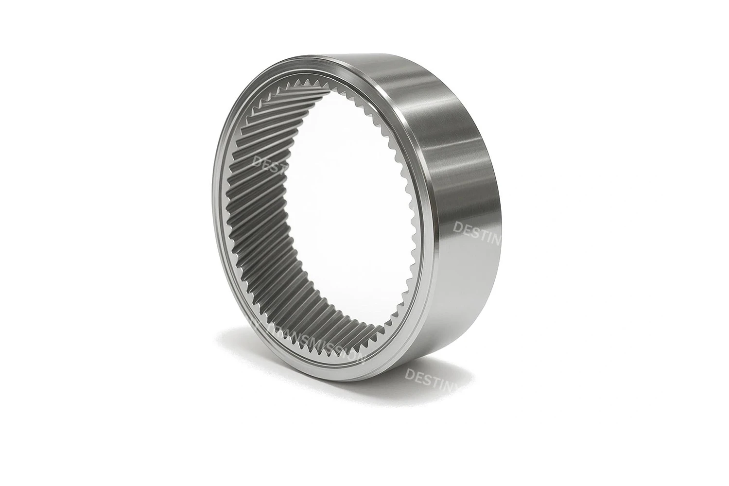
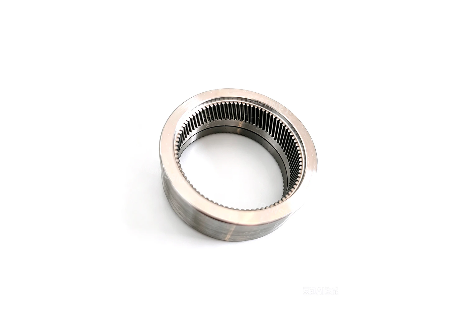
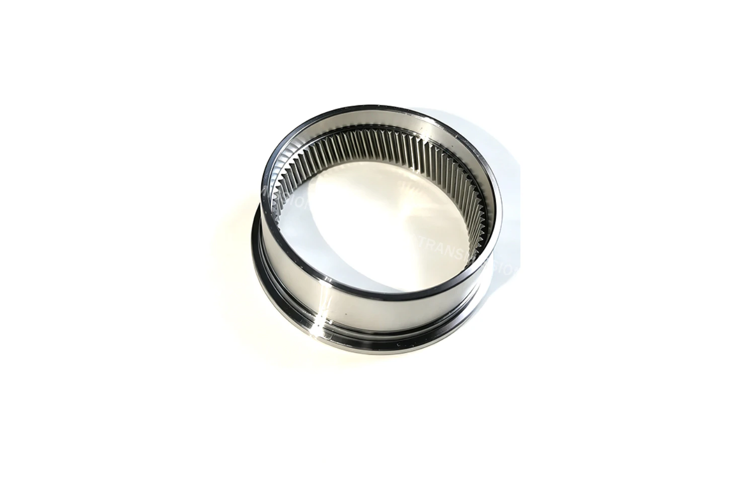
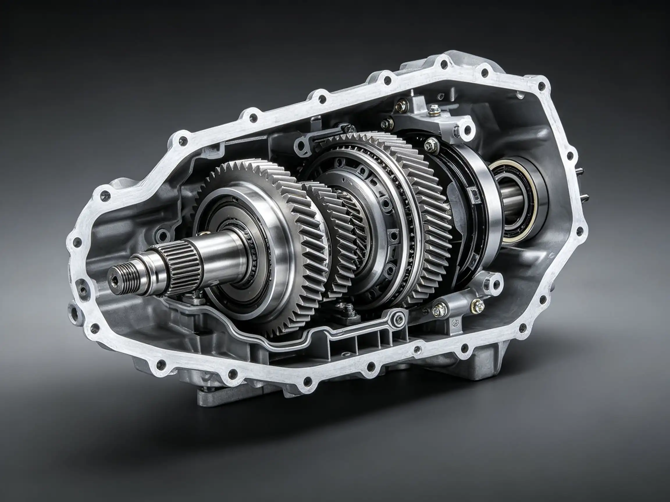
1.What is a Helical Internal Gear?
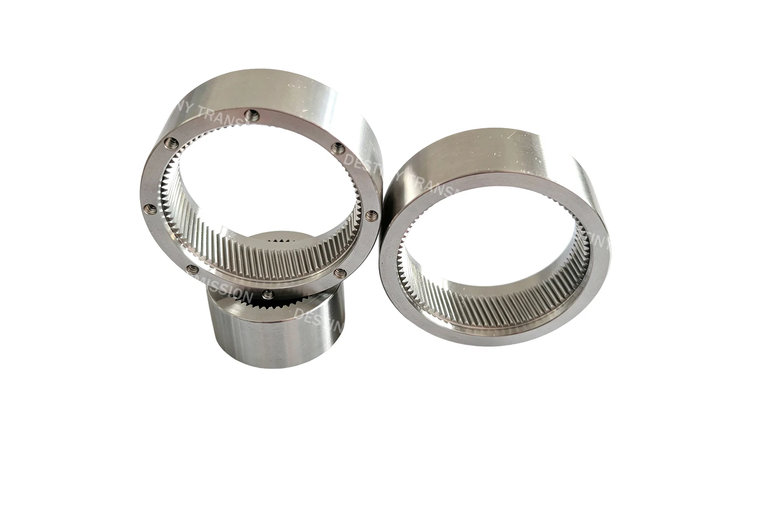
Helical internal gears, also known as helical internal cylindrical gears, are a widely used category of internal gearing solutions recognized for their superior transmission performance. Their teeth are uniformly machined along the inner circumference of the cylindrical body, with the tooth trace set at a constant helix angle relative to the gear axis. When paired with a mating helical external gear, they form an internal gear drive that transmits power and motion between two parallel shafts, with both shafts rotating in the same direction.
The core difference between helical and spur internal gears lies in their tooth trace geometry and meshing characteristics. For spur internal gears, the tooth trace runs perfectly parallel to the axis, meaning the entire tooth face engages and disengages at once — this leads to impact loads and noise during start-stop cycles. Helical internal gears, by contrast, feature a helical tooth form that engages and disengages gradually and progressively, resulting in smoother, more continuous power transmission.
In practice, helical internal gears are the preferred choice for heavy-duty, high-speed applications where smooth operation and low noise are required. They are the standard internal gear configuration used in planetary gear reducers, slewing drives, and precision gearboxes.
2. Core Structure & Transmission Characteristics
1.Tooth Profile & Helix Orientation Design
These gears feature a concave involute tooth profile that meshes with a mating helical external gear, delivering a constant transmission ratio with good tolerance for center distance deviations. The key distinction from spur internal gears is the helical tooth trace, which runs at a fixed helix angle relative to the gear axis — typically 15° to 25° as standard, with custom angles available on request.
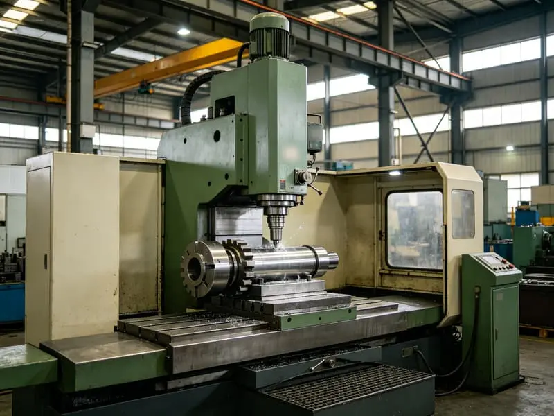
Limited by the internal ring geometry, these gears are most commonly produced via helical slotting and skiving processes; high-precision variants require an additional internal gear grinding step. The standard pressure angle is 20°, though non-standard specifications such as 14.5° can also be accommodated. Note that helical teeth generate axial thrust during operation, so bearing selection and housing support structure must be specified to match this load.
2.Meshing & Transmission Behavior
In an internal gear arrangement, the smaller external pinion meshes tangentially inside the ring gear. The center distance between the two shafts equals the difference between their respective pitch circle radii, and both shafts rotate in the same direction.
Unlike spur gears — where the entire tooth face engages and disengages simultaneously, creating rigid impact loads — helical gear teeth enter and exit mesh gradually. Combined with the increased axial contact ratio introduced by the helix angle, this results in a significantly higher total contact ratio and more teeth sharing the load at any given time. Tooth surface contact stress is reduced accordingly, giving helical internal gears over 30% higher load capacity than equivalently sized spur internal gears.
The nested internal layout also compresses the overall drive footprint. With smooth meshing action and uniform tooth wear, this configuration is well suited for high-speed gearboxes operating with enclosed oil bath lubrication.
3.Transmission Efficiency
Precision-grade helical internal gear systems achieve a transmission efficiency of 97.5% to 98.5%. While this figure is slightly lower than equivalent-precision spur gear drives — due to additional friction caused by axial thrust — the overall performance under heavy-duty, high-speed operating conditions is superior.
Load distribution across multiple teeth reduces unit pressure on the tooth surface. When paired with high-precision lead crowning, the meshing contact pattern can be further refined, leading to steady, gradual wear over extended service life. Both torque density per unit volume and service life outperform comparable spur gear designs.
4.Performance Limitations & Application Suitability
The axial thrust generated by the helical tooth form requires bearings with axial load capacity, making shaft and housing design slightly more complex and costly than spur gear alternatives. Machining processes and tooling also demand higher precision, and thin-walled large-diameter rings require tighter control over workholding distortion.
Even so, the advantages of high contact ratio, low impact loading and quiet operation are significant. Helical internal gears are the preferred choice for high-speed, heavy-duty applications where smooth, low-noise performance is critical. They are widely used as internal gear rings in precision planetary gear reducers, wind turbine slewing drives, industrial robot joints and similar systems.
For low-to-medium speed applications with steady loads where cost control is the priority, spur internal gears offer a more cost-effective solution.
 +86 184 3796 0706
 info@destinytrans.com