 +86 184 3796 0706
 info@destinytrans.com


Introduction: Why Are Helical Rack and Pinion Systems Used in Automation Equipment?
Rack and pinion systems convert the rotary motion generated by a motor or other drive devices into linear motion. They are widely used in automation equipment that requires reciprocating movement, long travel distances, or continuous linear motion. Compared with linear transmission methods such as ball screws, rack and pinion systems are more suitable for applications requiring long travel distances, relatively high linear speeds, and continuous operation.
In automated production lines, robots, CNC equipment, and material handling systems, rack and pinion systems often need to withstand repeated meshing and transmission loads during long-term operation. Compared with straight-tooth designs, helical gears and racks usually provide smoother meshing performance. They can help reduce impact and operating noise, making them suitable for equipment with higher requirements for transmission stability and load-carrying capacity.
However, helical gearing also generates axial forces during operation. Therefore, factors such as bearing load capacity, installation accuracy, and proper matching of pinion and rack parameters need to be considered during system design and installation.
Quick Reference: Key Features of Helical Rack and Pinion Systems
- Transmission Principle: Converts rotary motion into linear motion. Helical tooth engagement generally provides smoother operation and is well suited for continuous linear motion.
- Common Parameters: Module, number of teeth, helix angle, rack length, accuracy grade, and backlash should be determined according to the specific operating conditions.
- Typical Applications: Commonly used in automated production lines, CNC equipment, robotic motion systems, cutting equipment, and long-travel linear motion mechanisms.
- Key Characteristics: Compared with straight-tooth designs, helical gearing generally provides smoother meshing, but it also generates axial forces. Therefore, bearing capacity, installation accuracy, and proper pinion-and-rack parameter matching need to be considered.
1. What Is a Helical Rack and Pinion System?
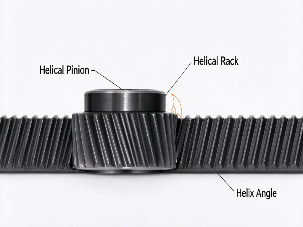
A helical rack and pinion system consists of a helical pinion and a helical rack. The helical pinion is mounted on the drive shaft, while the helical rack is fixed or installed along the required linear travel direction of the equipment. When the two components mesh, the rotational motion of the pinion drives the rack to move linearly, converting rotary motion into linear motion.
Compared with straight racks, helical racks have teeth arranged at an angle, allowing the pinion and rack to engage more smoothly during operation. The specific parameters should be determined according to the equipment’s load, operating speed, travel distance, and transmission requirements.
In practical equipment, this type of system is typically used together with a motor, reduction mechanism, and guide system. The pinion transmits the driving force, the rack converts rotary motion into linear displacement, and the guide system maintains stable movement and proper alignment.
2. How Does a Helical Rack and Pinion System Work?
A helical rack and pinion system is typically powered by a motor or servo motor. After passing through a reduction mechanism, the motor drives the helical pinion to rotate. The pinion then meshes with the rack and converts rotational motion into linear motion, moving a worktable, slide, or other actuator.
As the pinion rotates through a certain angle, the rack moves a corresponding linear distance. The number of teeth, module, and helix angle affect the linear displacement generated by each revolution of the pinion, while the pinion speed determines the linear travel speed of the rack. For equipment with long travel distances, the rack length needs to be determined according to the actual travel range and installation method. The helix angle also affects the meshing condition, transmission smoothness, and axial force.
In addition to motion speed and travel distance, transmission accuracy is another important consideration in system design. The machining accuracy of the pinion and rack, backlash, installation position, and parameter matching between the two components can all affect the final linear positioning accuracy. Therefore, in practical applications, suitable pinion and rack parameters should be selected according to the equipment’s load, speed, travel distance, and positioning requirements.
3. Why Choose a Helical Rack and Pinion Instead of a Straight Rack?
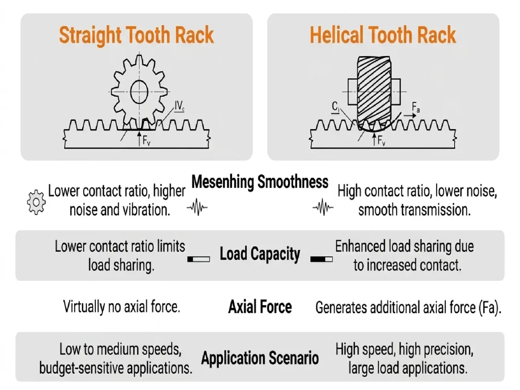
Compared with straight racks, helical racks feature angled tooth lines and generally have a higher contact ratio, resulting in more continuous tooth engagement. Under the same operating conditions, this design can reduce meshing impact and provide smoother linear motion.
The higher contact ratio also helps improve load distribution and running smoothness, making helical rack and pinion systems well suited for high-speed linear motion and automation equipment with stringent requirements for noise, vibration, and load-carrying capacity. In addition, multiple teeth can share the transmitted load, further improving the system’s load-carrying capability.
However, helical designs also have certain limitations. Because the teeth are angled, axial forces are generated during meshing. Therefore, the drive shaft assembly generally needs to be equipped with angular contact ball bearings or tapered roller bearings to accommodate the axial load. In applications requiring extremely high precision or very high load capacity, double-helical (herringbone) gears can also be used to offset the axial forces. During assembly, the relative positioning of the rack and pinion should be carefully controlled to prevent excessive local loading or accelerated wear caused by misalignment.
For high-speed, heavy-duty, or highly stable linear motion applications, helical racks generally offer greater advantages. For equipment with simpler structures and relatively low speed and load requirements, straight racks can also provide adequate performance.
4. Main Applications of Helical Rack and Pinion Systems
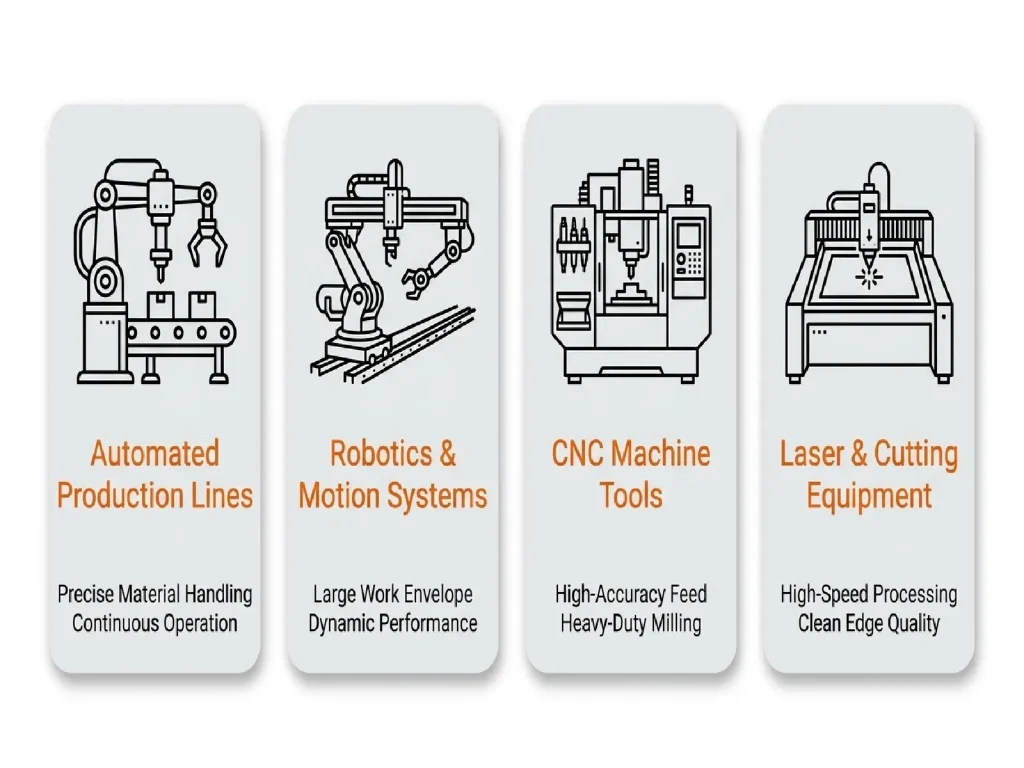
Helical rack and pinion systems are mainly used in equipment that requires stable linear motion, long travel distances, or relatively high operating speeds. In industrial applications, they are commonly used in automated production lines, robots, motion control systems, CNC machine tools, and cutting equipment.
In automated production lines, helical racks are often applied in moving platforms, feeding mechanisms, and linear actuators. They convert rotary drive into stable linear motion. For equipment that operates at high speeds or requires frequent reciprocating movement, the helical tooth design helps achieve smoother meshing performance.
In robots and motion control equipment, rack and pinion systems are used in linear slides, traveling axes, and other linear motion mechanisms. For applications requiring high positioning accuracy, factors such as pinion and rack machining accuracy, backlash, and installation precision can directly affect the final motion performance.
In CNC machine tools and large machining equipment, rack and pinion systems are suitable for long-travel linear motion mechanisms, including worktables and gantry structures. Compared with some short-stroke transmission methods, racks can be manufactured in longer sections to support larger travel ranges.
In addition, laser cutting machines, plasma cutting machines, conveying systems, and material handling equipment also commonly use rack and pinion systems for linear drive applications. These systems often require high operating speeds or long travel distances. Therefore, suitable rack and pinion parameters should be selected according to the load, speed, travel distance, and positioning requirements.
5. Key Factors Affecting the Performance of Helical Rack and Pinion Systems
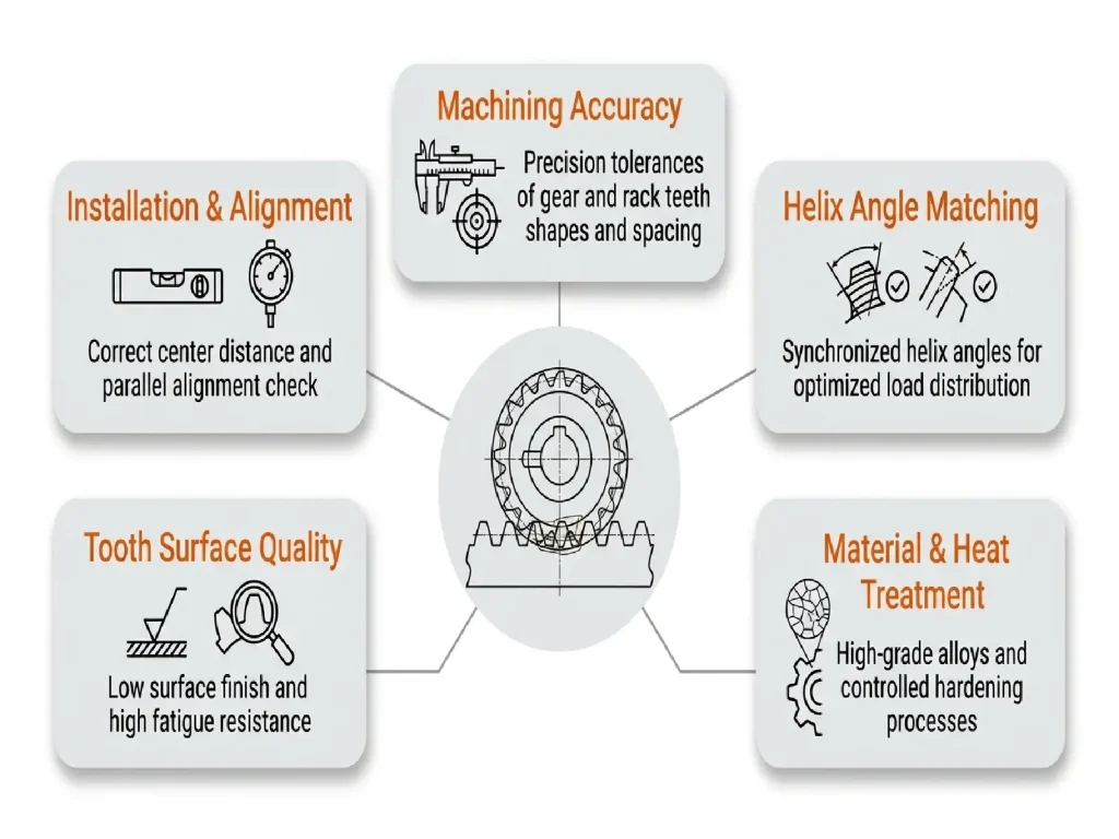
The performance of a helical rack and pinion system depends not only on the rack and pinion themselves, but also on machining accuracy, material selection, heat treatment, and installation conditions. These factors are closely interconnected, and significant deviations in any one of them can affect the accuracy and stability of linear motion.
Rack and Pinion Accuracy
Tooth profile, tooth pitch, and dimensional errors can affect the meshing condition between the rack and pinion. Insufficient machining accuracy may result in variations in backlash, vibration, or positioning errors during operation. Therefore, the machining accuracy of both the rack and pinion should be selected and controlled according to the equipment’s speed, load, and positioning requirements.
For high-precision transmission applications, the accuracy grade of the gear components is also an important consideration. With advanced machining equipment and inspection capabilities, helical racks and pinions can be manufactured with accuracy grades up to ISO Grade 4, helping meet the requirements of applications that demand high positioning accuracy and stable transmission performance.
Helix Angle and Parameter Matching
The helix direction, module, helix angle, and other parameters of the helical rack and pinion must be properly matched. Improper parameter selection may result in abnormal meshing, uneven tooth contact, or changes in axial force, affecting transmission stability.
Material and Heat Treatment
Material selection should be based on factors such as load, operating speed, working environment, and required service life. For systems operating under higher loads or for extended periods, suitable alloy steels can be selected according to the actual operating conditions, together with appropriate heat treatment processes to improve strength, wear resistance, and service life.
Tooth Surface Quality
Tooth surface roughness, machining errors, and local defects can all affect the meshing condition. Good tooth surface quality helps improve meshing performance, reduce friction, vibration, and noise during operation, and minimize wear over long-term use.
Installation and Alignment
Rack straightness, installation clearance, parallelism, and the positional relationship between the pinion shaft and rack all affect system performance. Even when the rack and pinion themselves have high machining accuracy, installation deviations can still result in localized tooth contact, increased running resistance, or uneven wear.
6. Common Materials and Manufacturing Processes for Helical Racks and Pinions
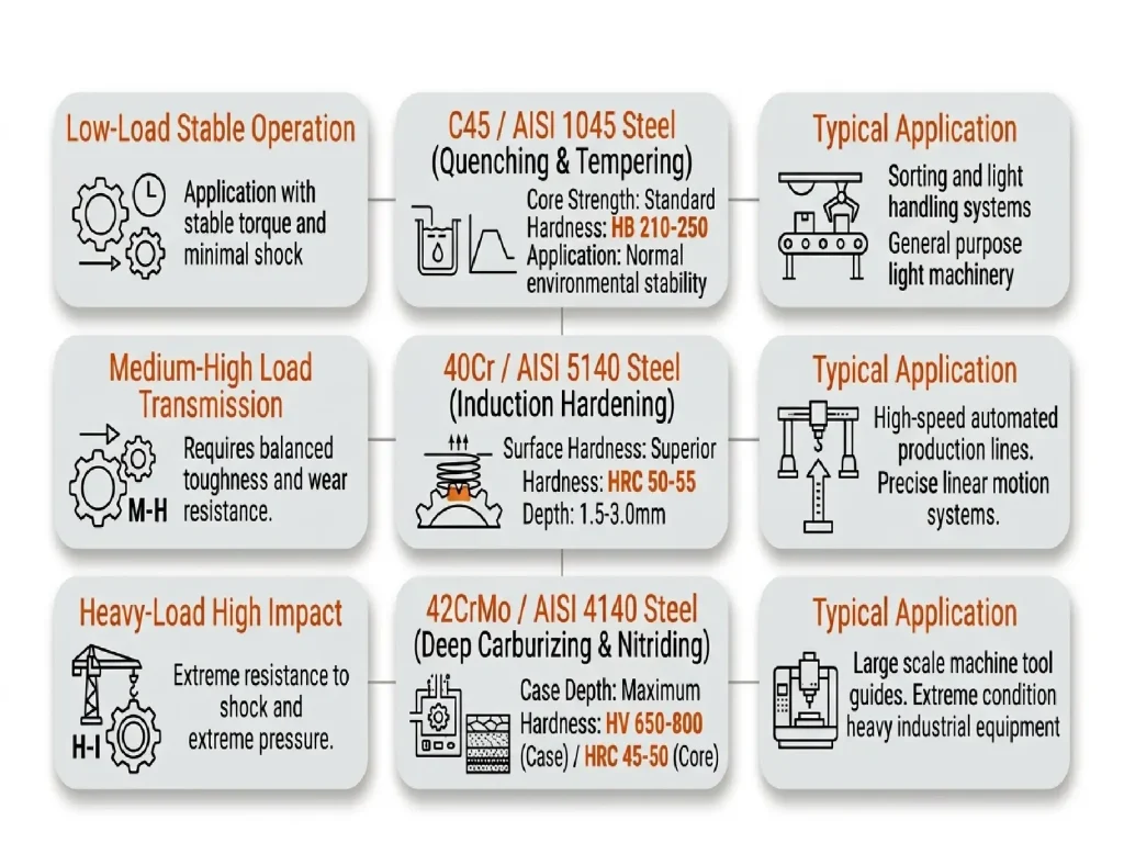
The materials and manufacturing processes for helical racks and pinions should be selected based on the load, operating speed, working environment, and required service life. Different operating conditions create different requirements for strength, wear resistance, and accuracy. Therefore, the material selection and heat treatment processes should be adjusted accordingly.
Common Materials for Helical Racks and Pinions
In terms of materials, C45 steel provides good machinability and cost-effectiveness. It is suitable for transmission systems operating under relatively low loads and stable conditions.
40Cr alloy steel offers good strength, toughness, and hardenability, making it suitable for medium- to high-load applications. 42CrMo alloy steel is more suitable for heavy-duty and high-torque transmission systems, especially those exposed to impact loads.
For special operating conditions, other alloy steels can also be selected according to specific application requirements.
Manufacturing Processes for Helical Racks and Pinions
During manufacturing, suitable machining methods should be selected according to the structure, dimensions, module, and accuracy requirements of the rack and pinion.
Depending on the gear structure, accuracy level, and production volume, pinions can be manufactured through processes such as gear hobbing, gear shaping, or gear milling. Racks can be produced using methods such as gear milling or form cutting.
The specific process should be determined based on product structure and manufacturing requirements. For applications requiring higher accuracy, additional finishing processes, such as post-heat-treatment finishing or gear grinding, may also be required.
Heat Treatment and Quality Inspection
Heat treatment is mainly used to improve material strength, hardness, wear resistance, and fatigue resistance. However, it may also cause dimensional changes and deformation.
Therefore, the heat treatment process should be coordinated with the selected material and gear structure. Appropriate machining allowances should be reserved for subsequent finishing operations.
Finally, the rack and pinion should undergo inspections for dimensions, tooth profile, tooth pitch, hardness, and surface quality. When necessary, meshing performance should also be checked after assembly.
Proper coordination between material selection, heat treatment, machining accuracy, and installation requirements helps the helical rack and pinion system maintain stable linear transmission performance during long-term operation.
7. How to Choose the Right Helical Rack and Pinion System?
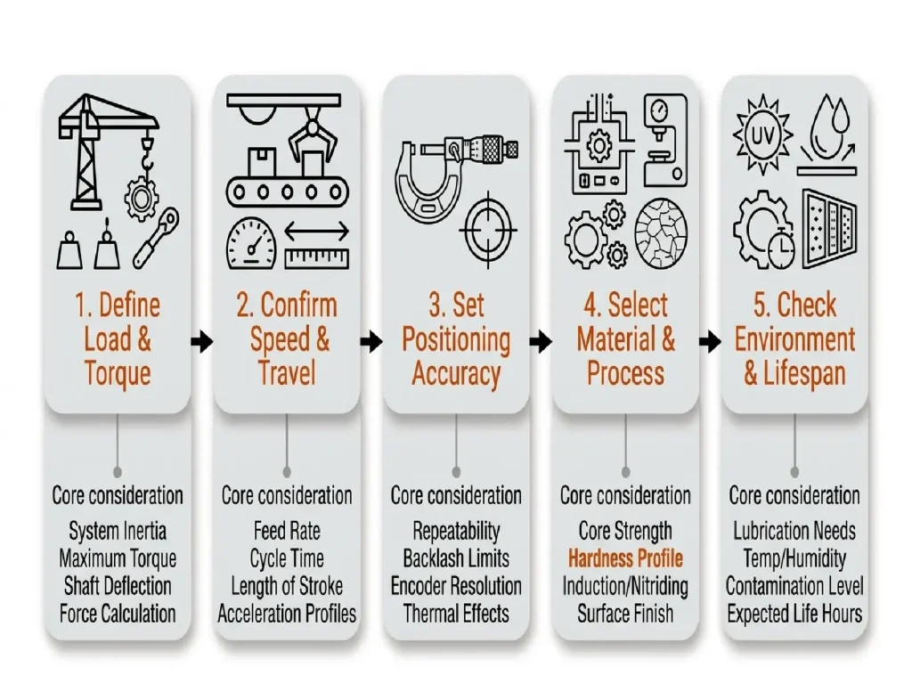
Selecting a helical rack and pinion system requires consideration of the actual operating conditions of the equipment. The selection process should not focus only on gear dimensions or materials. Factors such as load, operating speed, travel distance, positioning accuracy, working environment, and service life all influence system design and parameter selection.
For heavy-duty equipment, special attention should be given to the material strength, tooth surface hardness, and fatigue resistance of the rack and pinion. The appropriate module, face width, and pinion dimensions should be determined based on actual load requirements. For high-speed applications, factors such as tooth profile accuracy, tooth pitch accuracy, meshing conditions, and operating noise should be carefully evaluated. This helps prevent machining errors and installation deviations from affecting motion stability.
For long-travel equipment, rack length is not the only consideration. Rack installation straightness, connection methods, and meshing consistency between different rack sections also need to be evaluated. For high-precision positioning equipment, backlash, rack and pinion machining accuracy, and assembly errors should be carefully controlled to reduce positional deviations during transmission.
In addition, the working environment and operating duration of the equipment can affect system selection. Equipment used in high-temperature, dusty, humid, or continuous-duty environments requires proper consideration of material selection, heat treatment, lubrication, and surface treatment. For automation equipment produced in large quantities, the manufacturing consistency of racks and pinions should also be considered. This helps ensure stable assembly and operating performance across different production batches.
FAQ
1. What are the advantages of helical racks over straight racks?
Helical racks generally provide smoother meshing with the pinion. This makes them suitable for equipment with higher requirements for operating noise, vibration, and transmission stability. However, helical transmission also generates axial forces. Therefore, factors such as bearing capacity, assembly methods, and parameter matching should be considered during system design and installation.
2. What types of automation equipment are helical racks suitable for?
Helical racks are suitable for equipment that requires high-speed linear motion, long-travel transmission, or smooth operation. Common applications include automated production lines, robot motion systems, CNC equipment, laser cutting machines, and material handling equipment.
3. How is the helix angle of a helical rack determined?
The helix angle should be selected based on factors such as rack and pinion structure, load, operating speed, meshing requirements, and the resulting axial force. A larger helix angle does not always provide better performance. The selection should balance meshing smoothness and axial force according to the actual application requirements.
4. What parameters are required for customizing a helical rack?
A rack drawing or physical sample is generally recommended for customization. If a drawing is not available, the required information should include the module, number of teeth or rack length, helix angle and hand, accuracy grade (such as DIN 6 or DIN 8), tooth surface hardness (such as HRC 55–60), material, and heat treatment requirements.
Additional operating conditions should also be provided, including the mounting method, working load, operating speed, and travel distance. These details help determine the appropriate rack design and manufacturing process.
5. Can helical racks be customized based on samples?
Yes. For non-standard or replacement racks, customization can be performed based on a physical sample. The manufacturer can measure the sample to determine key parameters, such as the module, addendum, helix angle, and hand.
The actual dimensions and operating conditions can also be evaluated based on the wear condition of the original component. The appropriate machining and heat treatment processes can then be selected accordingly.


