 +86 184 3796 0706
 info@destinytrans.com


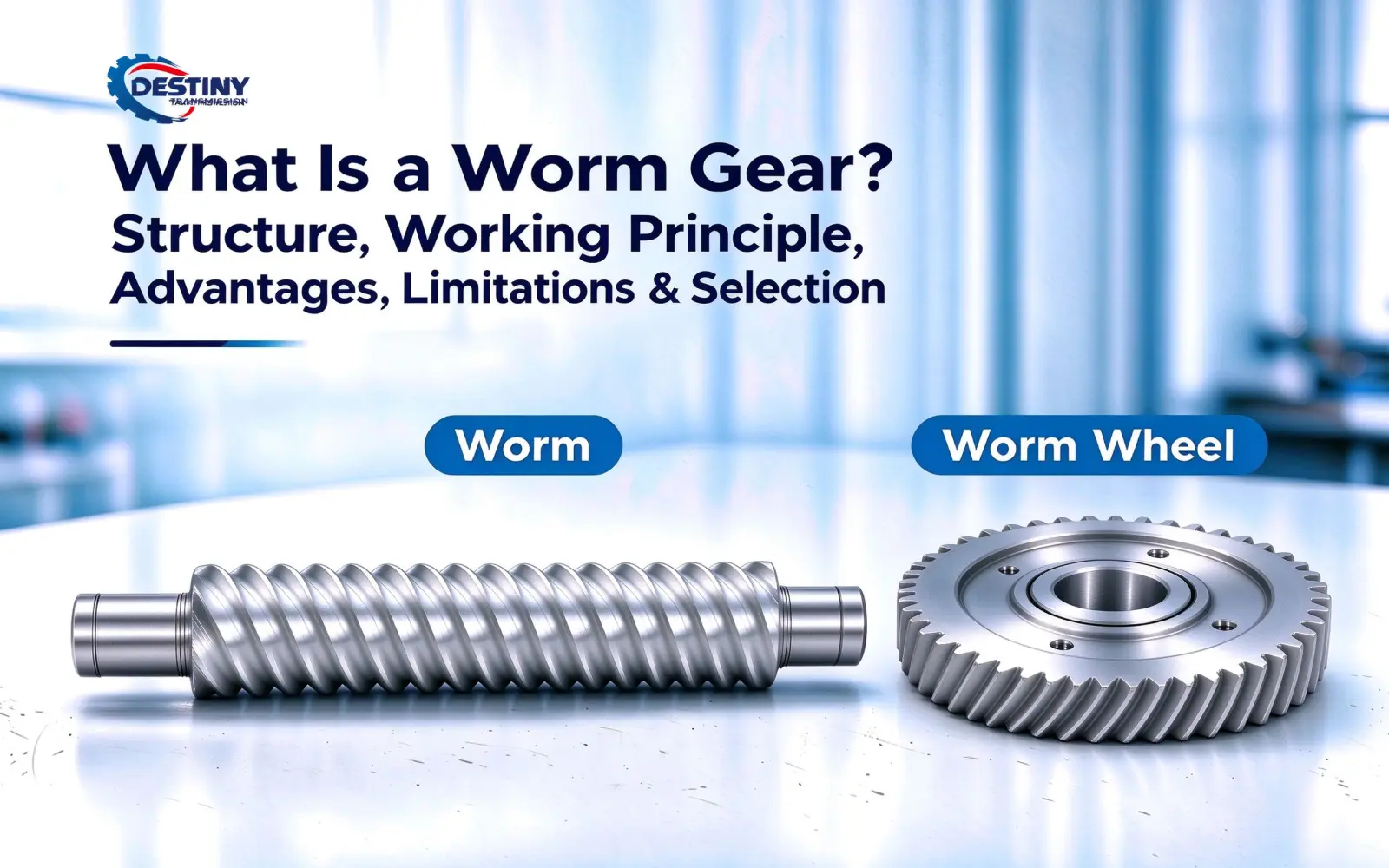
Introduction: What Is the Purpose of a Worm Gear?
Quick Answer: A worm gear set is a reduction transmission consisting of a worm and a worm wheel. The worm drives the worm wheel through sliding tooth contact, allowing a relatively large reduction ratio in a compact, crossed-shaft arrangement. Its main advantages include high reduction capability and compact construction, while its main limitations are sliding losses, heat generation, and tooth surface wear. Self-locking may occur under certain conditions, but it should not be assumed for every worm gear set.
In mechanical transmission systems, worm gearing is commonly used when equipment requires speed reduction, relatively high output torque, and a compact transmission arrangement. Unlike many cylindrical gear drives, a worm and worm wheel can transmit power between crossed shafts, with shaft arrangements close to 90° being common.
The main characteristic that distinguishes worm gearing from many other gear drives is the significant sliding contact between the worm and worm wheel. This sliding action contributes to its reduction capability and compact configuration, but it also affects efficiency, temperature rise, lubrication requirements, and tooth surface wear.
Selecting a worm gear set therefore requires more than specifying a reduction ratio. Input speed, output torque, duty cycle, lubrication, installation space, and required service life should be evaluated together to determine whether worm gearing is appropriate for the application.
1. What Are the Worm and Worm Wheel?
Worm gearing is a mechanical transmission system in which a worm meshes with a worm wheel to transmit motion and power. The worm resembles a screw and has continuous helical teeth on its surface, while the worm wheel is designed to mesh with the worm.
During operation, the worm is normally the driving member, while the worm wheel is the driven member. As the worm rotates, its helical tooth surface drives the worm wheel, changing the speed, torque, and direction of power transmission.
The two shafts in a worm drive are normally arranged as crossed shafts, with configurations close to 90° being common. Compared with some solutions that use multiple stages of cylindrical gears to achieve a large reduction ratio, worm gearing can combine speed reduction and a change in power transmission direction within a relatively compact structure.
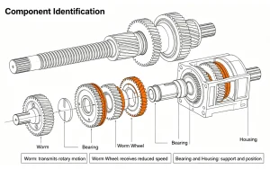
Basic Structure of a Worm Gear Set
| Component | Main Function |
| Worm | Transmits the input power and drives the worm wheel through its helical teeth |
| Worm Wheel | Receives motion and torque from the worm and delivers rotary output |
| Shafts | Support and transmit rotary motion |
| Bearings | Support rotating components and maintain their correct position |
| Housing | Secures and protects the transmission components while providing space for lubrication and sealing |
The design of an actual worm gear set also needs to consider center distance, number of worm starts, number of worm wheel teeth, lead angle, materials, manufacturing accuracy, and lubrication conditions. These parameters influence transmission performance and service life.
2. How Does a Worm Gear Work?
The operating process of a worm drive can be summarized as:
Worm rotates → drives worm wheel → reduces speed → delivers torque
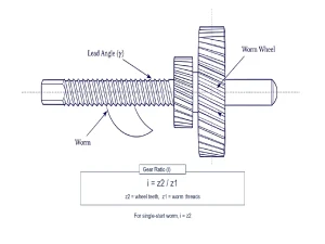
As the worm rotates, its helical teeth move along the worm wheel tooth surface and drive the wheel to rotate. The rotational speed of the worm wheel depends on the number of worm starts and the number of teeth on the worm wheel. With other conditions unchanged, a higher tooth count on the worm wheel or fewer worm starts results in a higher theoretical reduction ratio.
For a single-stage worm gear set, the theoretical reduction ratio can generally be expressed as:
Reduction ratio = Number of worm wheel teeth ÷ Number of worm starts
For example, if a worm gear set uses a single-start worm and a worm wheel with 40 teeth, the theoretical reduction ratio is approximately 40:1. Under ideal conditions, 40 turns of the worm would produce approximately one turn of the worm wheel.
A 40:1 ratio is only the theoretical reduction ratio and does not mean that 40:1 is automatically the correct choice. Actual selection should take into account the required output speed, output torque, transmission efficiency, temperature rise, operating conditions, and the required worm and worm wheel dimensions.
Why Does the Number of Worm Starts Matter?
The number of worm starts affects the reduction ratio, lead angle, transmission efficiency, and self-locking tendency. With the worm wheel tooth count unchanged, increasing the number of worm starts reduces the theoretical reduction ratio. At the same time, the lead angle increases, which generally helps improve transmission efficiency but reduces the tendency toward self-locking.
Single-start worms are often selected for higher reduction ratios, while multi-start worms are commonly considered when higher efficiency or output speed is required. Neither configuration is universally better; the appropriate choice depends on the required speed, torque, efficiency, and self-locking behavior.
3. Main Structural Features of Worm Gearing
1. Worm
The worm is the driving component of the transmission system. It resembles a screw, but its helical tooth form and geometric parameters must be determined according to the specific application.
Common parameters include the number of starts, lead, lead angle, diameter, tooth form, and manufacturing accuracy. These parameters influence the reduction ratio, efficiency, and load-carrying capacity.
The contact condition between the worm and worm wheel has a significant effect on transmission performance, making both manufacturing and assembly accuracy important. Uneven contact can increase noise, wear, and heat generation.
Worms are available in different profiles and configurations, and the appropriate type depends on the required meshing geometry, manufacturing method, and transmission characteristics. Therefore, when specifying a custom worm gear set, providing only the worm wheel tooth count and center distance is not sufficient. The specific worm type and relevant geometric parameters also need to be defined. ISO 10828:2024 covers common worm profiles and worm-and-worm-wheel mesh geometry.
2. Worm Wheel
The worm wheel works together with the worm and is the main component responsible for delivering the output motion and torque.
Because the two components experience significant sliding contact, material pairing is particularly important. A common combination is a steel worm paired with a copper alloy worm wheel, because this material pairing can provide suitable friction and wear characteristics under sliding contact.
There is no single fixed material combination. The choice should be based on factors such as load, speed, lubrication, operating environment, and required service life.
3. Shafts, Bearings, and Housing
A worm gear set normally works together with input and output shafts, bearings, and a housing to form a complete transmission assembly.
The shafts transmit rotary motion, the bearings support and position the rotating components, and the housing secures and protects the internal components while providing the conditions required for lubrication and sealing.
For equipment operating continuously or under relatively high loads, proper lubrication and heat dissipation are particularly important.
4. What Are the Main Advantages of Worm Gearing?
The main advantages of worm gearing are related to its reduction capability, structural arrangement, and transmission configuration.
1. High Reduction Ratios in a Compact Structure
Worm gearing can achieve relatively large reduction ratios in a single stage and within a compact structure, making it suitable for transmission systems requiring low speed and high torque output. The practical ratio depends on the worm type, number of starts, worm wheel tooth count, and overall design.
2. Compact Structure
The crossed-shaft arrangement allows worm gearing to fit flexibly into equipment with limited internal space. This can be an advantage in mechanical systems where installation space is restricted.
3. Relatively Smooth Meshing
The worm and worm wheel transmit motion through helical tooth contact. Appropriate tooth geometry, manufacturing accuracy, and lubrication conditions can help reduce impact and vibration during operation. Actual noise and vibration levels are also affected by assembly quality, load, and operating conditions.
4. Self-Locking May Occur Under Certain Conditions
Some worm gear sets can exhibit a degree of self-locking under specific conditions, making it difficult for the load side to back-drive the worm.
However, self-locking is not an inherent or guaranteed characteristic of every worm drive. Its actual behavior depends on the lead angle, friction conditions, lubrication state, load, and specific design. In lifting equipment and other applications with high safety requirements, this characteristic should not be relied upon as a substitute for dedicated braking or safety mechanisms.
Self-locking should therefore be regarded as a transmission characteristic that may occur under specific operating conditions rather than as an assumed safety function during selection.
5. What Are the Limitations of Worm Gearing?
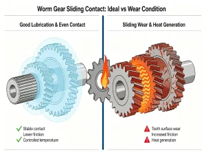
One of the most important characteristics of worm gearing is its sliding contact. While this provides certain advantages, it also introduces several limitations.
1. Efficiency May Be Lower Than That of Some Other Gear Drives
Because there is significant relative sliding between the worm and worm wheel, part of the mechanical energy is converted into heat through friction. As a result, transmission efficiency can be lower than that of other gear drive types under certain operating conditions.
Efficiency is closely related to the lead angle, friction conditions, materials, lubrication, and rotational speed. In general, a smaller lead angle corresponds to a larger reduction ratio and a stronger tendency toward self-locking, but it also results in greater sliding losses.
2. Temperature Rise Needs Attention During Continuous Operation
Friction losses are converted into heat. Temperature rise becomes more important during high-speed, heavy-load, or long-duration operation. Appropriate lubrication, material selection, and heat dissipation design can help control the operating temperature.
There is no single “safe temperature rise” value that applies to all worm drives. The allowable temperature depends on factors such as reducer design, lubricant, ambient temperature, load, and the manufacturer’s thermal power rating. Therefore, it is more reliable to check the specific product’s thermal rating and lubrication requirements during selection. A fixed temperature limit should not be applied to all applications.
A publicly available industrial case study from a steel mill in Egypt reported a failure of a worm gear reducer after approximately 1.25 years of operation with mineral oil lubrication. After changing the lubricant to Mobil Glygoyle 220, the reported operating temperature decreased by 25°C. The service life also increased to approximately 10 years. These results were specific to the equipment, operating conditions, and lubricant used. They should not be treated as a general prediction of service life.
3. Tooth Surface Wear Requires Close Control
The worm and worm wheel are exposed to continuous sliding contact, and wear is closely related to material pairing, lubrication, load, and operating speed.
Insufficient lubrication, unsuitable material selection, or prolonged operation beyond the design conditions can accelerate tooth surface wear and may eventually lead to increased backlash, higher noise levels, and a shorter service life.
6. Where Is Worm Gearing Commonly Used? When Is It a Good Choice?
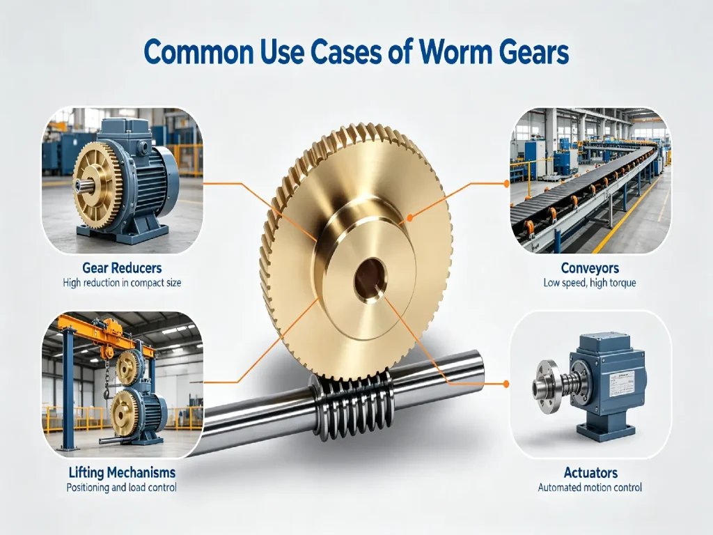
Worm gearing is mainly used in mechanical equipment requiring speed reduction, low-speed output, relatively high output torque, or compact installation. However, it is not necessarily the best solution for every reduction application. Therefore, factors such as efficiency, input speed, duty cycle, and lubrication conditions should also be evaluated.
Industrial Gear Reducers
Worm gear reducers can convert the high rotational speed of a motor into a lower output speed while providing the required output torque. This is why they are widely used in industrial transmission equipment. They can be advantageous in applications requiring a relatively large reduction ratio and compact construction.
Conveying Equipment
In some conveyor and material-handling systems, worm gearing can reduce motor speed and provide the required output torque. For conveyors operating continuously for long periods, transmission efficiency, temperature rise, and lubrication conditions require particular attention.
Lifting, Positioning, and Adjustment Equipment
Some lifting, vertical movement, positioning, and adjustment mechanisms require low operating speeds and relatively high output torque. Worm gearing can be used in some of these transmission arrangements.
The self-locking characteristic under certain conditions may also provide value in specific applications. However, equipment with high safety requirements should still use reliable braking or safety mechanisms.
Automation Equipment and Actuators
In some automated machinery, actuators, and adjustment mechanisms, worm gearing can provide speed reduction and a change in power transmission direction within limited installation space. It can therefore be used in valve drives, actuators, and other systems requiring low-speed rotation and relatively high output torque.
When Is Worm Gearing a Suitable Choice?
Worm gearing is generally a good choice when compact size, a relatively large reduction ratio, and crossed-shaft transmission are important. It is less attractive when very high efficiency, high input speed, or continuous high-duty operation is the primary requirement.
When an application places greater emphasis on high transmission efficiency, long-term continuous operation, or high input speed, the efficiency losses and temperature rise caused by sliding friction should be carefully evaluated. These factors should also be compared with other reduction solutions such as helical gears and planetary gears.
The key is determining whether the transmission type matches the actual operating conditions.
7. How Does Worm Gearing Differ From Other Gear Types?
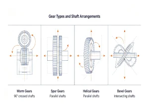
Different gear transmission types have different areas of application. Actual selection should take into account requirements such as reduction ratio, efficiency, speed, transmission direction, and installation space.
| Gear Type | Main Characteristics | Common Limitations |
| Worm Gearing | Relatively large reduction ratios, compact structure, suitable for crossed-shaft transmission | Significant sliding friction; efficiency and temperature rise require attention under some operating conditions |
| Spur Gears | Simple structure, relatively easy to manufacture, high transmission efficiency | Mainly used for parallel-shaft transmission; single-stage reduction range is limited |
| Helical Gears | Smooth meshing, good load capacity, suitable for relatively high speeds | Generate axial thrust and therefore place additional requirements on bearings and structural design |
| Bevel Gears | Suitable for intersecting shafts and capable of changing the direction of power transmission | Tooth geometry and manufacturing requirements are relatively complex |
In simple terms, worm gearing is suitable for crossed-shaft arrangements and applications requiring relatively large reduction ratios, but efficiency and temperature rise need to be carefully balanced. Spur and helical gears are more commonly used for parallel-shaft transmission, while bevel gears are mainly used to transmit power between intersecting shafts.
8. How to Choose the Right Worm Gear Set?
When selecting a worm gear set, it is not enough to consider only the reduction ratio or overall dimensions. The decision should be based on the equipment’s actual operating conditions and transmission requirements.
Required Output Speed / Reduction Ratio: Start with the required output speed and calculate the required reduction ratio from the input speed. Then determine a suitable combination of worm starts and worm wheel teeth.
Input Speed: Input speed affects sliding friction, temperature rise, and lubrication requirements. For higher-speed applications, transmission efficiency and heat dissipation should be evaluated carefully.
Output Torque: Confirm that the selected worm gear set can handle the required continuous torque, starting torque, and potential shock loads. Where applicable, a suitable service factor should also be considered. This depends on the duty cycle and load characteristics.
Duty Cycle: Continuous and intermittent operation place different demands on temperature rise, lubrication, and service life. Selection should therefore reflect the actual duty cycle.
Material Pairing: The materials of the worm and worm wheel should be selected based on load, speed, lubrication conditions, operating environment, and required service life. A steel worm paired with a copper alloy worm wheel is common. However, the actual choice should be based on the specific operating conditions.
Lubrication Conditions: Proper lubrication methods and lubricants help reduce friction and wear while controlling operating temperature. High-speed or continuous-duty applications generally place greater demands on lubrication.
Installation Space: In addition to overall dimensions, consider the center distance, shaft diameter, axial length, mounting orientation, and interfaces with other components. This ensures that the worm gear set can be installed correctly and meet the equipment’s space requirements.
For a custom worm gear set, the manufacturer will typically need information such as worm type, number of starts, worm wheel tooth count, center distance, dimensions, materials, accuracy requirements, input speed, output torque, lubrication method, duty cycle, and order quantity.
Relevant Standards and Design References
Relevant standards include GB/T 10085-2018, GB/T 10089-2018, ISO 10828:2024, and ISO/TS 14521:2020. These standards cover basic parameters, accuracy, worm profiles, mesh geometry, and load capacity calculation.
ISO/TS 14521:2020 remains the published edition currently available. ISO 14521:2026 is under publication and is intended to replace it.
9. Frequently Asked Questions
1. Does a Worm Gear Always Provide Self-Locking?
No. Whether self-locking occurs depends on the lead angle, friction conditions, lubrication state, load, and specific design.
2. Is Worm Gearing Efficient?
Transmission efficiency depends on factors such as reduction ratio, lead angle, materials, lubrication, speed, and load. Because of the significant sliding friction involved, efficiency may be lower than that of other gear transmission types under certain operating conditions.
3. What Materials Are Commonly Used for Worms and Worm Wheels?
A common combination is a steel worm paired with a copper alloy worm wheel, but the specific materials should be selected according to load, speed, lubrication conditions, and required service life.
4. Why Does Worm Gearing Generate Heat?
The main reason is sliding friction during meshing. Heat generation becomes more significant under high-speed, heavy-load, or long-duration operation, making proper lubrication and heat dissipation important.
5. Is Worm Gearing Suitable for High-Speed Operation?
Yes, but with limitations. Worm gearing can be used at relatively high speeds in some applications, but increasing input speed also increases sliding losses, heat generation, and lubrication demands.
6. Why Are Worms and Worm Wheels Often Made From Different Materials?
Because significant sliding occurs between the worm and worm wheel, the material combination directly affects friction, wear, and service life. A steel worm paired with a copper alloy worm wheel is common in engineering applications, but this is not a fixed combination. The specific materials should still be selected based on load, speed, lubrication, and service life requirements.
Conclusion
Worm gearing is suitable for a wide range of mechanical equipment requiring speed reduction and crossed-shaft transmission. However, its sliding contact also creates specific requirements related to efficiency, temperature rise, and tooth surface wear.
In practical selection, factors such as reduction ratio, output torque, input speed, efficiency, materials, lubrication conditions, and duty cycle should be evaluated together. For custom worm gearing, it is also necessary to confirm the worm type, dimensions, materials, manufacturing accuracy, operating speed, load, and lubrication requirements. This helps ensure that the transmission components match the operating requirements of the specific equipment.
In short, worm gearing is a suitable choice when a relatively large reduction ratio, compact construction, and crossed-shaft transmission are important. Its efficiency, heat generation, and wear characteristics should also be acceptable for the application.


