 +86 184 3796 0706
 info@destinytrans.com



Introduction: What Is a Gear Tooth Profile?
Quick Answer:
A gear tooth profile is the geometric shape of an individual tooth on the end face of a gear. It determines the basic contact relationship between mating gears during meshing and affects how motion and load are transmitted. The selected tooth profile must also match the gear’s geometric parameters, operating conditions, and manufacturing requirements.
1. What Is a Gear Tooth Profile?
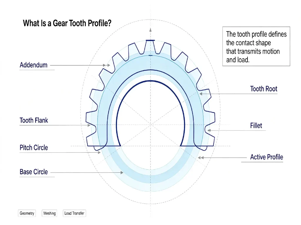
A gear tooth profile is the contour of an individual tooth on the end face of a gear, or the geometric curve that defines the tooth flank. During operation, the teeth use this profile to engage with the mating gear and transmit motion and load.
The tooth profile involves geometric elements such as the addendum, dedendum, tooth flank, pitch circle, and base circle. The pitch circle is mainly used to define the nominal geometry of the gear, while the base circle is the reference circle from which the involute tooth flank is generated. The theoretical design defines an ideal tooth profile, but the actual tooth flank is also affected by manufacturing errors, installation errors, and elastic deformation under load. In engineering practice, actual tooth profile deviations therefore need to be controlled through design, manufacturing, and inspection.
2. Why Does Tooth Profile Affect Gear Performance?
When two gears mesh, each tooth enters the meshing zone, carries load, and then leaves contact as the next tooth pair engages. The tooth profile determines how this contact progresses along the line of action. A properly designed tooth profile helps maintain the intended relative motion and contact relationship throughout the meshing cycle. This is related to the concept of conjugate profiles, which are mating profiles designed to maintain the required relative motion and velocity relationship during meshing. In practical gear design, the mating tooth profiles must maintain this defined geometric relationship so that the driven gear rotates at the intended speed ratio.
If tooth profile deviations are excessive, the actual contact position and load distribution may change, potentially leading to the following problems:
Increased transmission error:
Excessive tooth profile deviation can cause the actual meshing relationship to differ from the theoretical condition, increasing transmission error and affecting motion transmission accuracy.
Greater meshing impact and vibration:
When tooth profile errors affect the contact transition as teeth enter and leave mesh, the resulting load fluctuations and meshing impact can become more pronounced. At high operating speeds, this may increase meshing excitation and make noise and vibration more noticeable.
Localized wear and tooth surface damage:
When the load is concentrated over a smaller contact area, local contact stress and sliding may increase, making abnormal wear, pitting, and other tooth surface damage more likely during long-term operation.
Therefore, the tooth profile does more than define what the gear tooth looks like. It directly affects the actual meshing quality and operating condition of the gear.
3. What Is an Involute Tooth Profile?
The involute tooth profile is one of the most widely used tooth profiles in modern industrial gears. It is commonly found in spur gears and helical cylindrical gears.
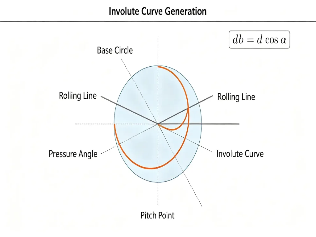
An involute is the curve traced by a point on a straight line as the line rolls without slipping along a base circle. In gear design, the working tooth flank generally uses a section of the involute generated from the base circle.
For an involute gear, the pressure angle determines the relationship between the pitch circle and the base circle. A larger pressure angle results in a smaller base circle relative to the pitch circle. It also changes the direction of the force transmitted between mating teeth. Therefore, tooth profile design needs to be determined together with parameters such as module, pressure angle, and number of teeth.
In the design of standard involute cylindrical gears, the basic rack tooth profile also needs to be considered. It provides an important reference for defining the basic tooth profile and related geometric parameters. These parameters include pressure angle, addendum, and clearance.
For cylindrical gears used in general and heavy engineering, GB/T 1356-2001[1] specifies the standard basic rack tooth profile. It adopts the same basic profile specified in ISO 53:1998[2].
For a standard involute gear, the relationship between the base circle diameter (db), pitch circle diameter (d), and pressure angle (α) is:
db = d cos α
The involute function is also commonly used in involute geometry calculations:
inv α = tan α − α
where α is the pressure angle expressed in radians. In practical gear calculations, the involute function describes the geometric relationship between the pressure angle and the involute tooth profile.
The widespread use of the involute profile is partly due to its stable meshing characteristics. It is also related to the long-term development of manufacturing processes such as hobbing and shaping.
Within a certain range of center distance variation, involute gears can maintain relatively good meshing adaptability. This is one important reason for their long-standing use in industrial transmission systems.
4. Which Parameters Affect Tooth Profile Design?
The tooth profile needs to be determined based on the overall geometric relationship of the gear and its operating conditions. In actual design, in addition to the basic tooth profile, the following parameters also need to be considered:
| Parameter | Main Influence on Tooth Profile or Meshing |
| Module | Determines the basic gear dimensions and affects related geometric dimensions such as tooth height and tooth thickness. It needs to match the gear size and load requirements. |
| Tooth Thickness & Backlash | Tooth thickness affects the geometric relationship between teeth and tooth spaces. Proper backlash helps prevent interference between non-working flanks while allowing for manufacturing errors and operating conditions. |
| Pressure Angle | Affects the direction of force during gear meshing and is related to radial force, tooth root strength, and meshing characteristics. |
| Tooth Number & Profile Shift | The number of teeth affects tooth profile geometry and meshing conditions. For gears with a small number of teeth, appropriate profile shift can reduce the risk of undercutting and adjust tooth thickness and tooth root dimensions. |
| Addendum & Clearance | Determine tooth height and radial clearance during meshing. For a standard basic rack tooth profile, commonly used standard gearing has an addendum coefficient ha* = 1 and a clearance coefficient c* = 0.25. Actual design still needs to be based on the applicable tooth system and specific requirements. |
| Contact Ratio | Describes the continuity of tooth contact during meshing. For spur gears, the main parameter is the transverse contact ratio εα. For helical gears, the overlap ratio εβ also needs to be considered, with the total contact ratio given by εγ = εα + εβ. |
| Gear Type | Spur gears, helical gears, and bevel gears have different geometric relationships and meshing methods, so their tooth profile design methods also differ. |
| Operating Conditions | Load, speed, impact level, and accuracy requirements affect tooth profile and modification design. High-speed gears place greater emphasis on smooth meshing and noise, while heavy-duty gears focus more on contact conditions and load-carrying capacity. |
5. What Are the Common Types of Gear Tooth Profiles?
Different tooth profiles have different meshing characteristics and areas of application. In addition to the widely used involute profile, other profiles such as cycloidal profiles are also used, as well as specialized tooth forms for specific transmission applications.
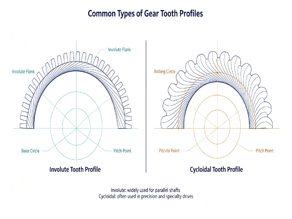
1. Involute Tooth Profile
The involute profile has a mature system of design, calculation, and manufacturing and is widely used in common industrial transmissions such as spur gears and helical cylindrical gears.
2. Cycloidal Tooth Profile
The cycloidal profile differs from the involute profile in both tooth geometry and meshing characteristics. It generally involves profiles generated by epicycloids or hypocycloids and is relatively common in traditional clocks, instruments, and similar mechanisms. Some specialized transmission mechanisms also use tooth profiles based on cycloidal principles.
3. Other Specialized Tooth Profiles
Some transmission systems use specialized tooth profiles when conventional involute or cycloidal profiles cannot provide the required motion characteristics, contact conditions, or load capacity. These profiles are normally developed for specific mechanisms rather than general-purpose cylindrical gears.
6. What Is Gear Tooth Profile Modification?
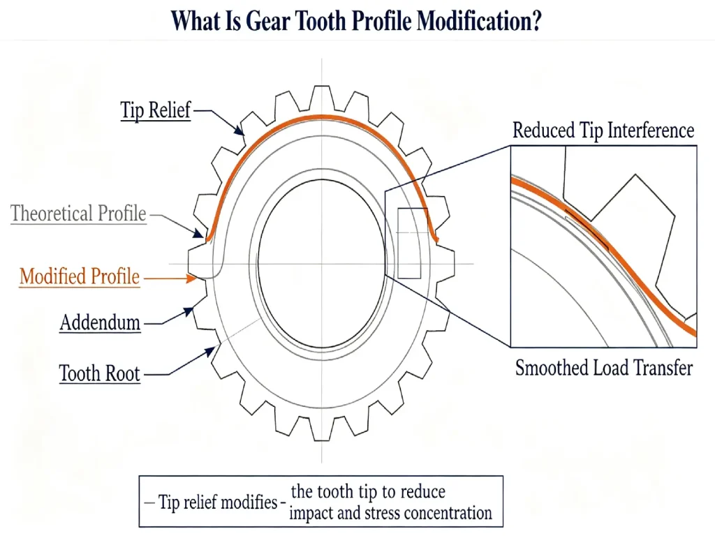
The theoretical tooth profile is defined under ideal geometric conditions. In actual operation, however, gears are affected by load, rotational speed, installation errors, and elastic deformation of the gear and shaft, causing the actual contact condition to differ from the theoretical condition. Making targeted adjustments to local areas of the theoretical tooth profile is known as profile modification.
Common methods include tip relief and other adjustments to specific portions of the working tooth profile. The main purpose of profile modification is to control the contact condition under load, reduce meshing impact, and improve load distribution. In high-speed applications, appropriate modification can also help reduce transmission error and dynamic excitation.
It is important to note that more profile modification is not necessarily better. Insufficient modification may not effectively reduce meshing impact, while excessive modification may reduce the effective contact area, worsen load distribution, and affect load-carrying capacity. The amount of modification therefore needs to be determined according to load, speed, gear dimensions, deformation, and accuracy requirements.
Profile modification and lead modification are also different.
Profile modification changes the tooth shape along the profile direction, mainly from the root toward the tip. Lead modification changes the tooth surface geometry along the face width, mainly affecting how contact is distributed across the tooth width. For high-speed, heavy-duty, or high-precision gears, both may need to be applied together based on the actual operating conditions.
7. How Is Gear Tooth Profile Inspected?
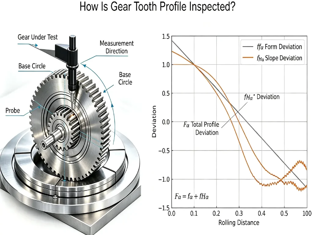
After gear machining is completed, basic dimensions such as outside diameter and tooth thickness are checked, but tooth profile accuracy also needs to be evaluated. For high-precision cylindrical involute gears, a gear measuring machine is commonly used to compare the measured tooth flank with the theoretical profile.
For cylindrical involute gears, ISO 1328-1:2013[3] defines relevant flank accuracy grades and deviation terms. Tooth profile evaluation includes the following items:
| Inspection Item | Symbol | Main Meaning |
| Total Profile Deviation | Fα | Reflects the overall deviation of the actual tooth profile from the theoretical tooth profile. |
| Profile Form Deviation | ffα | Reflects the degree to which the actual tooth profile shape deviates from the mean profile line. |
| Profile Slope Deviation | fHα | Evaluates the inclination of the mean profile line relative to the theoretical profile over the evaluation length and reflects the overall slope of the actual tooth profile. |
Actual inspection results are usually presented as measurement curves or inspection reports and are used to determine whether the tooth profile deviation falls within the limits specified by the drawing and applicable accuracy requirements.
How Should Tooth Profile Inspection Results Be Interpreted?
A gear inspection report normally compares the measured tooth flank with the theoretical profile. It also records the corresponding deviation values. Fα, ffα, and fHα should not be evaluated independently. They need to be considered together with the specified accuracy grade, evaluation range, and drawing requirements.
A result that is acceptable for one gear application may not be suitable for a higher-precision or higher-speed transmission.
If the actual tooth profile deviation exceeds the design or accuracy requirements, it may lead to uneven meshing, increased transmission error, greater noise and vibration, and localized wear. Therefore, tooth profile inspection is not only part of dimensional inspection. It is also an important method for evaluating actual meshing quality and manufacturing accuracy.
8. How Do You Choose the Right Gear Tooth Profile?
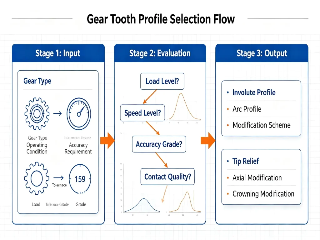
Selecting a suitable gear tooth profile requires consideration of the gear type, basic geometry, operating conditions, modification requirements, and manufacturing accuracy.
Determine the Gear Type
Establish whether the gear is a spur gear, helical cylindrical gear, bevel gear, or another gear type. Different gear types have different geometric relationships and meshing conditions, so the applicable tooth profile system must be identified first.
Define the Basic Tooth Profile and Geometry
For most conventional industrial cylindrical gears, the involute profile is normally used. Its basic geometry needs to be determined together with parameters such as module, pressure angle, number of teeth, tooth thickness, backlash, and profile shift.
Evaluate Profile and Lead Modification
The need for profile modification and lead modification depends on the actual operating conditions. High-speed, heavy-duty, or high-precision transmissions may require modification to control contact conditions, reduce meshing impact, and improve load distribution. The amount of modification should be determined based on factors such as load, speed, gear dimensions, deformation, and accuracy requirements.
Verify the Finished Gear Through Inspection
After manufacturing, the actual tooth profile and lead should be inspected according to the drawing and applicable accuracy requirements. For high-precision cylindrical gears, measurement results can be used to verify whether the actual tooth flank remains within the specified tolerance range.
FAQ
1. What Is a Gear Tooth Profile?
A gear tooth profile is the geometric contour of an individual tooth on the end face of a gear. It determines the basic contact relationship between mating gears and affects motion and load transmission.
2. What Is the Most Common Gear Tooth Profile?
The involute profile is one of the most common tooth profiles in modern industrial gears and is widely used for spur gears and helical cylindrical gears.
3.Why Is the Involute Profile Widely Used in Industrial Gears?
The involute profile provides a well-established geometric system for motion transmission and manufacturing. Its geometry is compatible with common gear manufacturing processes such as hobbing and shaping, and it can maintain the intended velocity ratio despite moderate center-distance variation. These characteristics have contributed to its widespread use in industrial cylindrical gears.
4. Does Tooth Profile Affect Gear Noise?
Yes. Tooth profile errors can increase transmission error and meshing excitation, which are more likely to appear as noticeable noise and vibration at high operating speeds.
5. What Is Gear Tooth Profile Modification?
Profile modification means adjusting local areas of the theoretical tooth profile according to actual load, deformation, and operating conditions. One common example is tip relief.
6. What Is the Difference Between Tooth Profile and Lead?
Tooth profile describes the tooth flank geometry in the profile direction, while lead describes the tooth flank geometry along the face width. Profile deviations and lead deviations therefore describe errors in two different geometric directions.
7. Why Is Tooth Profile Accuracy Important?
Large tooth profile deviations can change the actual contact condition and lead to transmission error, uneven load distribution, noise, vibration, and localized wear. Tooth profile accuracy is therefore an important control item in gear manufacturing and quality inspection. deviations relevant to flanks of gear teeth. Geneva: International Organization for Standardization, 2013.


