 +86 184 3796 0706
 info@destinytrans.com


Introduction
In mechanical engineering design, assembly line automation, and plant maintenance operations (MRO), selecting the correct industrial gearbox (speed reducer) dictates drive system reliability, mechanical service life, and overall energy efficiency. An oversized gearbox drives up initial procurement costs and causes physical space interferences; an undersized unit leads to thermal overheating, tooth failure, and premature bearing wear.
This engineering guide outlines the essential technical parameters and duty-cycle factors required to size a speed reducer accurately, helping engineers and procurement teams match the right model within minutes.
1. Core Power and Gear Ratio Parameters (Calculation Baseline)
Determining gearbox frame size and gear contact strength begins with basic kinetic calculations. Sizing requires at least two of the following values to calculate the missing specifications:
-
Input Power (P1) and Motor Specifications:
-
Motor power ratings (in kW or HP) and nominal motor input speed (n1).
-
Standard 4-pole (4P) AC induction motors run at approximately 1400 to 1480 rpm (50 Hz) or 1750 rpm (60 Hz); 6-pole (6P) motors run at roughly 960 rpm.
-
Prime mover type: Standard AC induction motor, variable frequency drive (VFD) inverter-duty motor, permanent-magnet synchronous servomotor, or hydraulic/air motor.
-
-
Reduction Ratio (i) or Output Speed (n2):
-
Calculated via the formula: Ratio (i) = n1 / n2.
-
For example, with an input speed of 1400 rpm and a target machine speed of 56 rpm, the required ratio is i = 25.
-
-
Required Output Torque (T2):
-
The actual working torque required at the driven shaft (measured in Nm), calculated as: Torque (T2) = (9550 * P1 * efficiency) / n2.
-
2. Mechanical Layout and Mounting Interfaces
Physical footprint constraints on plant floors dictate the required shaft alignment and mounting style:
-
Inline / Coaxial: Input and output shafts share the same axis. Typical models include R Series helical gearboxes and cycloidal pinwheel reducers, ideal for inline conveyor drives.
-
Parallel Shaft: Input and output shafts run parallel but offset. Typical models include F Series parallel-shaft helical gearboxes, featuring flat housings designed to tuck into narrow machine profiles.
-
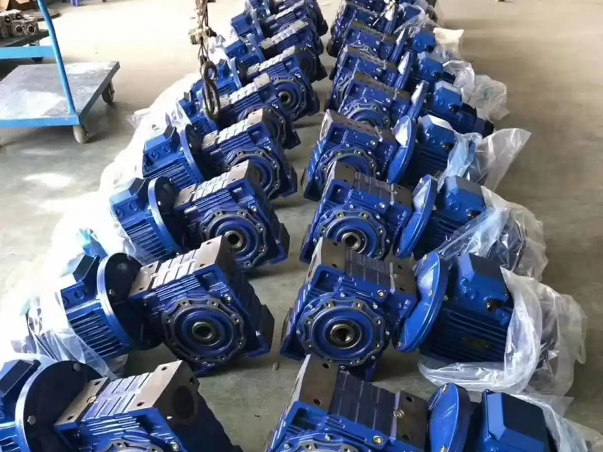
90-Degree Right-Angle: Input and output shafts intersect or cross at 90 degrees. Common designs include K Series helical-bevel gearboxes, S Series helical-worm gearboxes, and NMRV aluminum worm gear reducers, allowing motors to sit flush along conveyor frames.
-
Solid Output Shaft: Connected via flexible couplings, chain sprockets, or timing pulleys. Requires verification of shaft diameter tolerance, keyway width, and shaft extension length.
-
Hollow Output Shaft (Shaft-Mounted): Slides directly onto the driven machine’s head shaft. Available with standard keyways or keyless shrink discs, eliminating flexible couplings and utilizing torque reaction arms to absorb counter-torque.
-
Mounting Styles: Foot-mounted (horizontal base pads) or flange-mounted (B5 large flange / B14 face flange).
3. Operating Conditions and Service Factor (fs)
Catalog torque ratings are baseline lab figures measured under uniform load. Practical engineering requires applying a Service Factor (fs) to ensure the gearbox achieves its design lifespan:
-
Daily Operating Hours: Intermittent duty (< 8 hours/day), 16 hours/day, or continuous 24/7 duty.
-
Uniform Load (fs = 1.0 to 1.2): Centrifugal water pumps, liquid agitators, light belt conveyors.
-
Moderate Shock (fs = 1.3 to 1.6): Food mixers, machine tool feeds, hoists, industrial winches.
-
Heavy Shock & Frequent Starts/Stops (fs >= 1.7 to 2.0+): Mining rock crushers, vibrating screens, rolling mills, heavy stamping presses.
-
Overhung Radial and Axial Loads (Fr / Fa): When the output shaft connects via sprockets, gears, or narrow V-belts, external overhung loads pull on the output shaft, requiring bearing capacity verification.
4. Mounting Orientation and Environmental Factors
-
Mounting Position Codes (M1 to M6): M1 represents standard horizontal mounting; M4 represents vertical output shaft pointing down; M5 represents vertical output shaft pointing up.
-
Vertical Lubrication Protection: Vertical orientations (M4/M5) require increased oil fill levels, double lip oil seals, and elevated breather vents to keep upper bearings lubricated without causing seal leakage.
-
Ambient Operating Temperature: Standard operations range between -10°C and 40°C. Sub-zero environments (below -20°C) or high-temperature metal casting shops require specialized synthetic polyalphaolefin (PAO) or polyalkylene glycol (PAG) lubricants.
-
Ingress Protection & Special Ratings: Outdoor wet installations require upgraded IP65/IP66 enclosure protection and anti-corrosive paint. Food lines require NSF-H1 food-grade lubricants, and hazardous areas require ATEX/Ex explosion-proof certification.
5. Quick Sizing Data Sheet & RFQ Checklist
Providing the following dataset directly to the gearbox engineering team enables rapid turnaround on CAD drawings, dimensional verification, and pricing:
| Sizing Parameter | Client Application Data | Reference Example |
| Motor Power & Input Speed | [ ] kW / [ ] rpm | 3.0 kW / 1440 rpm (4-pole motor) |
| Target Output Speed / Ratio | Speed: [ ] rpm / Ratio: [ ] | n2 = 48 rpm (Ratio i = 30) |
| Drive Architecture | [ Inline / Parallel / Right-Angle ] | 90° Right-Angle Helical-Bevel (K Series) |
| Mounting & Output Style | [ Foot / Flange / Shaft-Mounted ] | Hollow Shaft with Torque Arm (Bore Ø40mm) |
| Mounting Position Code | [ M1 / M2 / M3 / M4 / M5 / M6 ] | M1 Standard Horizontal |
| Daily Duty & Shock Level | [ ] hrs/day; [ Uniform / Moderate / Heavy ] | 16 hrs/day; Moderate Shock (target fs >= 1.4) |
| Auxiliary Options | [ Specify accessories ] | Holding brake, VFD cooling fan, backstop |
Plant Maintenance (MRO) Tip: For direct drop-in replacement of existing machinery drives, take a clear photo of the original metal manufacturer nameplate (displaying full model codes, ratio, and serial number) and measure the shaft diameter, center height, and bolt hole centers. Manufacturers can supply an exact dimensionally interchangeable unit.
Conclusion & Request a Technical Sizing Review
Accurately matching an industrial speed reducer balances performance reliability against initial capital investment. Specifying motor parameters, mechanical layout, output torque, and service factors early streamlines engineering verification and guarantees trouble-free commissioning.
Need CAD 2D/3D models, replacement sizing assistance, or a factory-direct quotation?


