 +86 184 3796 0706
 info@destinytrans.com


Introduction
Industrial equipment often uses a motor and gear reducer to match motor speed with the operating requirements of the driven machine.
Industrial Equipment → Motor → SF Gear Reducer → Speed Reduction → Solid Shaft Output → Driven Equipment
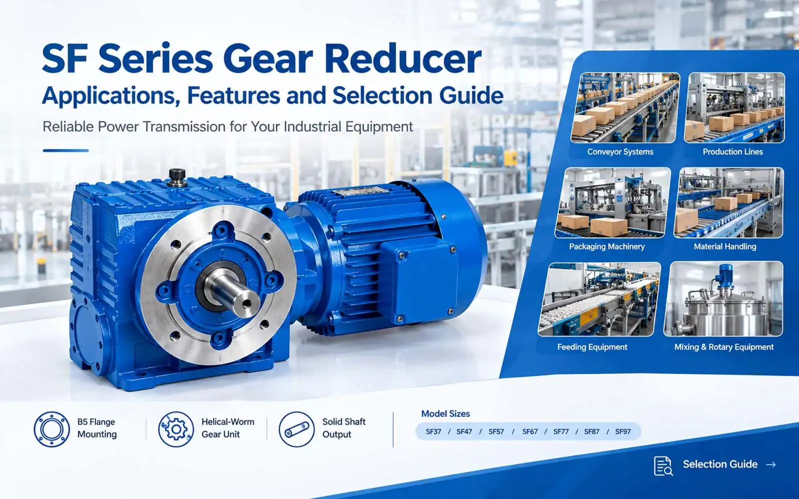
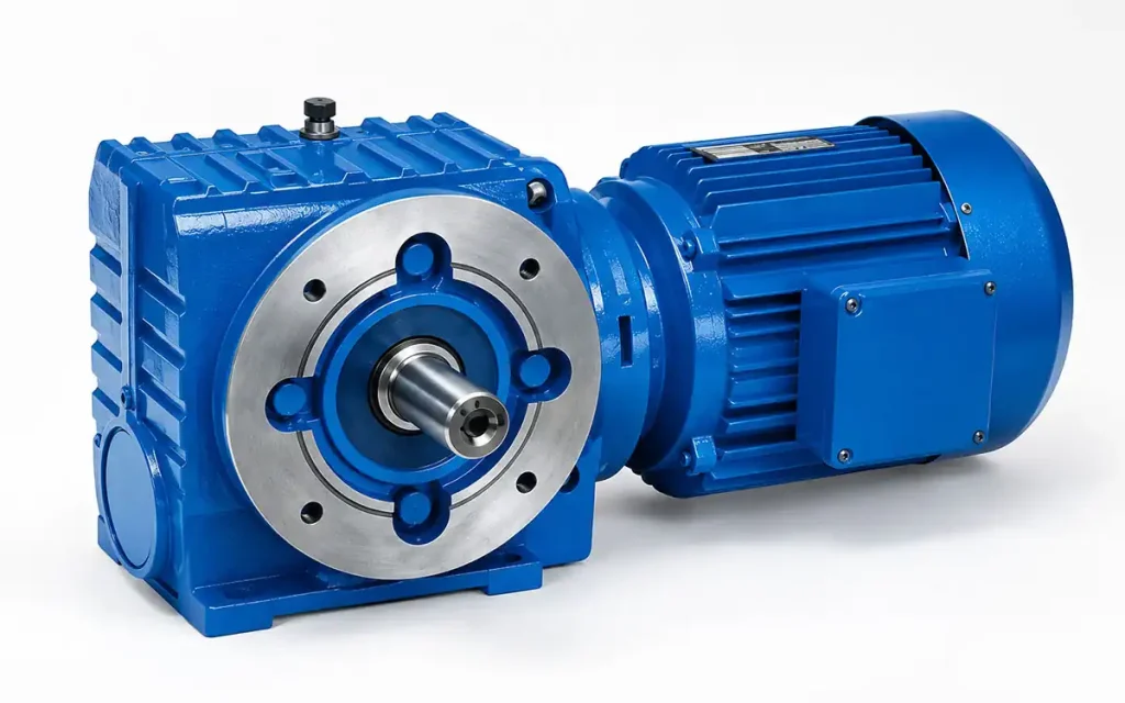
The SF Series Gear Reducer features a B5 flange-mounted structure, a helical-worm gear unit, and a solid shaft output for integration into motor-driven equipment.
Models from SF37 to SF97 are available in different sizes and mounting dimensions. Selection can be based on equipment structure, output connection, motor arrangement, and available installation space.
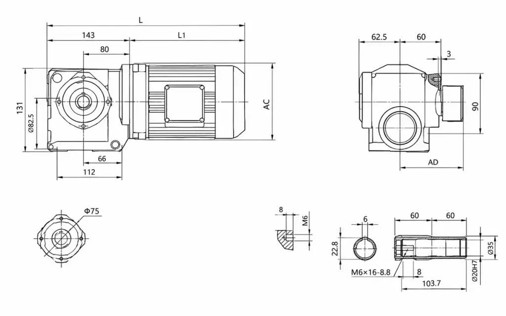
Technical drawings can be reviewed to confirm flange mounting details, output dimensions, motor connection requirements, and equipment installation space.
1. Why Do Industrial Machines Need a Gear Reducer?
1.1 Motor Speed and Machine Operation
Industrial motors often operate at speeds that may not directly match the operating requirements of the driven equipment.
A gear reducer is placed between the motor and the machine to reduce rotational speed and provide a more suitable output.
1.2 Basic Power Transmission Process
A typical transmission system follows:
Motor → Gear Reducer → Driven Equipment
The motor provides the input, the gear reducer adjusts the speed, and power is transmitted to the driven equipment for operation.
1.3 Equipment Drive Requirements
Drive requirements vary by machine. Common factors include:
- Motor input
- Required output speed
- Driven equipment
- Installation conditions
These details provide the basis for selecting the appropriate SF Series model and installation arrangement.
2. SF Series Gear Reducer Features and Technical Characteristics
The SF Series combines motor connection, helical-worm transmission, B5 flange mounting, and solid shaft output within an industrial drive arrangement.
2.1 B5 Flange-Mounted Structure
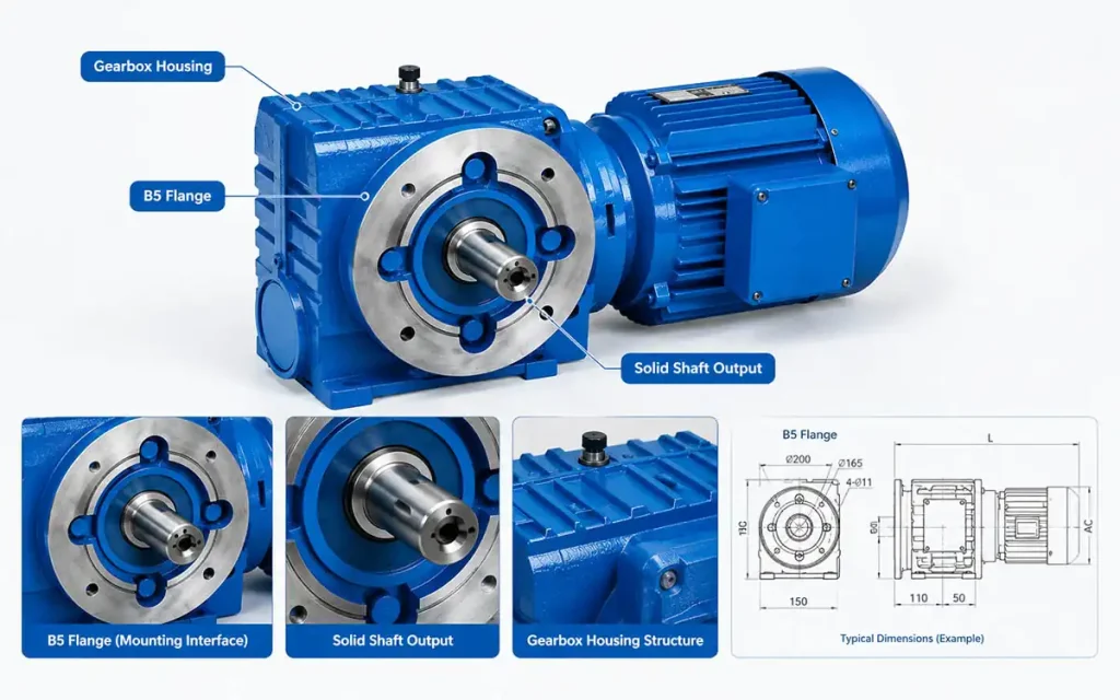
The SF Series uses a B5 flange-mounted structure.
The flange arrangement provides an installation interface between the gear unit and the equipment mounting structure. Flange dimensions and mounting details should be reviewed based on the required installation position.
2.2 Helical-Worm Gear Unit Arrangement
The SF Series is a helical-worm gear unit used in motor-driven transmission systems.
It provides speed reduction between the motor and the connected equipment.
2.3 Solid Shaft Output and Equipment Connection
The SF configuration uses a solid shaft output for connection to the driven equipment.
Shaft dimensions, connection methods, and the driven arrangement should be confirmed during selection.
2.4 Different Model Sizes and Mounting Dimensions
The SF Series includes:
- SF37
- SF47
- SF57
- SF67
- SF77
- SF87
- SF97
Different model sizes provide different overall dimensions and mounting details. The selected size should fit the equipment structure and available installation space.
2.5 Motor Connection and Equipment Layout
The motor connection forms part of the overall drive configuration between the motor and the SF gear reducer.
Motor connection should be configured according to the selected drive arrangement and motor installation requirements. The motor position and connection arrangement should also be considered as part of the overall equipment layout.
2.6 Technical Drawing Review
Technical drawings can be reviewed before ordering to confirm:
- B5 flange dimensions
- Mounting dimensions
- Solid shaft details
- Motor connection
- Available installation space
3. Why Choose an SF Series Gear Reducer?
The SF Series can be used as part of a motor-driven transmission system for industrial equipment requiring speed reduction and mechanical power transmission.
3.1 Supports Equipment Drive Integration
The SF Series can be incorporated into equipment as part of the overall drive system.
Its configuration can be matched with the motor, transmission components, and driven machine according to the required drive arrangement.
3.2 Supports Mechanical Drive Connections
The solid shaft output provides a direct mechanical interface for connecting the gear unit to the machine transmission system.
The connection arrangement should be selected according to the driven equipment and the required method of power transmission.
3.3 Suitable for Continuous and Repeated Machine Operation
Conveying, material transfer, feeding, and production equipment often operate continuously or through repeated cycles.
The drive system should therefore be configured according to the operating requirements of the specific application.
3.4 Adapts to Different Equipment Configurations
Different equipment designs may require different mounting positions, shaft connections, and drive layouts.
The appropriate SF model can be selected according to these configuration requirements and the available installation conditions.
4. SF Series Gear Reducer Applications in Different Industries
4.1 Conveyor Systems
Keywords:
- Conveyor Gearbox
- Conveyor Drive Gearbox
- Conveyor Gear Reducer
- Industrial Conveyor Drive
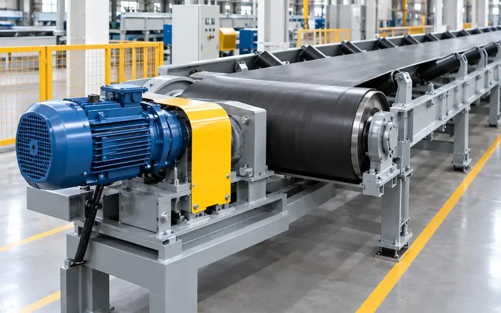
Conveyor systems use reduced-speed transmission to support material movement and continuous operation.
Typical applications include:
- Belt conveyors
- Roller conveyors
- Chain conveyors
A typical drive arrangement can be:
Motor → SF Gear Reducer → Solid Shaft → Conveyor Drive
Motor connection, solid shaft output, and flange-mounted installation can be configured according to the conveyor layout and connection requirements.
4.2 Material Handling and Transfer Equipment
Keywords:
- Material Handling Gearbox
- Material Transfer Gearbox
- Industrial Transfer Drive
Material handling equipment often operates through continuous transfer or repeated movement.
Typical applications include:
- Material transfer units
- Transfer mechanisms
- Handling conveyors
The motor and SF gear reducer can form part of the equipment drive system. The flange mounting arrangement can also be considered during machine layout and installation.
4.3 Production Line Equipment
Keywords:
- Production Line Gearbox
- Manufacturing Equipment Gearbox
- Industrial Machine Drive
Production lines may include conveyors, assembly machines, and transfer sections that require motor-driven transmission.
A typical arrangement is:
Motor → SF Gear Reducer → Driven Equipment
Drive configuration depends on the motor connection, output connection, equipment structure, and installation arrangement.
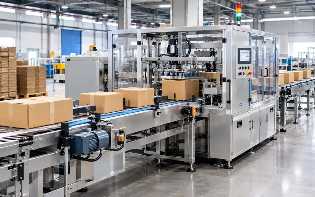
4.4 Packaging Machinery
Keywords:
- Packaging Machine Gearbox
- Packing Machine Gear Reducer
- Packaging Equipment Drive
Packaging machinery may include conveying, feeding, and sorting sections operating through repeated cycles.
Typical applications include:
- Carton conveyors
- Packing machines
- Sorting equipment
The SF Series can be incorporated into these machine sections according to the motor arrangement, output connection, and available installation space.
4.5 Feeding Equipment
Keywords:
- Feeding Machine Gearbox
- Feeder Drive Gearbox
- Industrial Feeder Gear Reducer
Feeding equipment may require reduced-speed transmission for continuous material supply or repeated feeding operations.
Typical examples include:
- Automatic feeders
- Material feeding machines
- Conveyor feeding systems
Motor input, required output speed, and the connection between the drive unit and feeding mechanism are key configuration factors.
4.6 Processing Equipment
Keywords:
- Processing Machine Gearbox
- Industrial Processing Gear Reducer
- Machine Drive Gearbox
Processing equipment may use a gear reducer as part of a motor-driven transmission system.
Typical applications include:
- Small processing machines
- Material processing equipment
- Production machinery
The SF configuration can be considered where the equipment requires speed reduction, shaft-based power transmission, and installation based on the machine structure.
4.7 Mixing and Rotary Equipment
Keywords:
- Mixer Gearbox
- Agitator Gearbox
- Rotary Equipment Gearbox
Speed reduction can provide a lower rotational speed for mixing and other rotary processes.
Typical applications include:
- Small mixers
- Agitators
- Rotary processing equipment
Selection can be based on the required operating speed, reduction ratio, output connection, shaft requirements, and installation dimensions.
5. How to Select the Right SF Series Gear Reducer?
A practical selection process can follow:
Machine Requirements → Drive Configuration → Model Selection → Installation Review
Motor Input
Identify the basic motor information:
- Motor power
- Motor type
- Input requirements
These details define the starting point for the drive configuration.
Output Speed
Determine the required operating speed based on the machine application, such as:
- Conveyor operation
- Feeding processes
- Production equipment
- Rotary operation
The required output speed should support the intended machine operation.
Reduction Ratio
Calculate the required reduction ratio from:
- Motor speed
- Required output speed
The selected ratio determines the speed reduction between the motor and the driven equipment.
Solid Shaft Output Arrangement
Verify the mechanical connection requirements, including:
- Shaft dimensions
- Output connection
- Driven equipment
- Transmission arrangement
The shaft configuration should be compatible with the connection between the gear unit and the driven machine.
B5 Flange Mounting Requirements
Compare the mounting requirements with the equipment structure:
- Flange dimensions
- Mounting position
- Equipment structure
- Installation arrangement
The selected mounting configuration should correspond to the available installation position and machine layout.
Installation Dimensions
Review the following dimensions before finalizing the model:
- Overall dimensions
- Mounting dimensions
- Shaft position
- Available installation space
SF37–SF97 models have different dimensions and installation arrangements. The selected model should be evaluated against the actual equipment layout.
Motor Connection
Confirm the motor-to-gearbox arrangement, including:
- Motor connection
- Motor installation
- Drive arrangement
- Equipment configuration
The motor connection should be configured as part of the overall machine drive system.
Technical Drawing Review
Technical drawings can be reviewed before ordering to verify:
- B5 flange mounting details
- Gear unit dimensions
- Solid shaft dimensions
- Motor connection
- Installation space
This review helps identify possible dimensional or connection issues before installation.
OEM Requirements
For OEM projects, provide the relevant equipment information, including:
- Motor requirements
- Output connection
- Flange mounting arrangement
- Installation dimensions
- Equipment layout
The final SF configuration can then be evaluated based on the machine structure, transmission connection, and installation requirements.
6. FAQ
Q1: What type of gearbox is the SF Series?
The SF Series is a B5 flange-mounted helical-worm gear unit with a solid shaft output.
Q2: What is an SF Series gear reducer used for?
It can be used in conveyors, transfer equipment, production machinery, and feeding systems.
Q3: Can the SF Series be used for conveyor systems?
Yes. Typical applications include belt, roller, and chain conveyors.
Q4: What is the B5 mounting arrangement?
It is a flange-mounted configuration for equipment installation.
Q5: Does the SF Series have a solid shaft output?
Yes. The solid shaft can connect the gear unit to driven equipment.
Q6: What model sizes are available?
The technical drawing includes models from SF37 to SF97.
Q7: What should be considered when selecting an SF gearbox?
Motor input, output speed, reduction ratio, shaft connection, flange mounting, and installation dimensions.
Q8: Can the SF Series fit different equipment layouts?
Yes. The model can be selected according to the equipment structure and available installation space.
Q9: Can technical drawings be reviewed before ordering?
Yes. Drawings can confirm flange dimensions, shaft details, motor connections, and installation space.
7. Conclusion
If you are configuring an SF Series gear reducer for conveyors, transfer systems, production lines, packaging machinery, feeders, processing equipment, or rotary machines, prepare the following information:
- Motor information
- Required output speed
- Reduction ratio
- Output shaft requirements
- B5 flange mounting requirements
- Equipment installation dimensions
Send us your equipment details or installation drawing for an SF Series configuration review.
Based on the motor arrangement, transmission connection, and available installation space, we can help review the model configuration, flange mounting details, solid shaft connection, motor connection, and OEM project requirements.


