 +86 184 3796 0706
 info@destinytrans.com


Introduction
Industrial equipment uses mechanical transmission systems to transfer power from the drive source to the driven shaft and connected equipment.
Drive Source → SAT/SHT Gear Reducer → Hollow Shaft Connection → Driven Shaft → Equipment
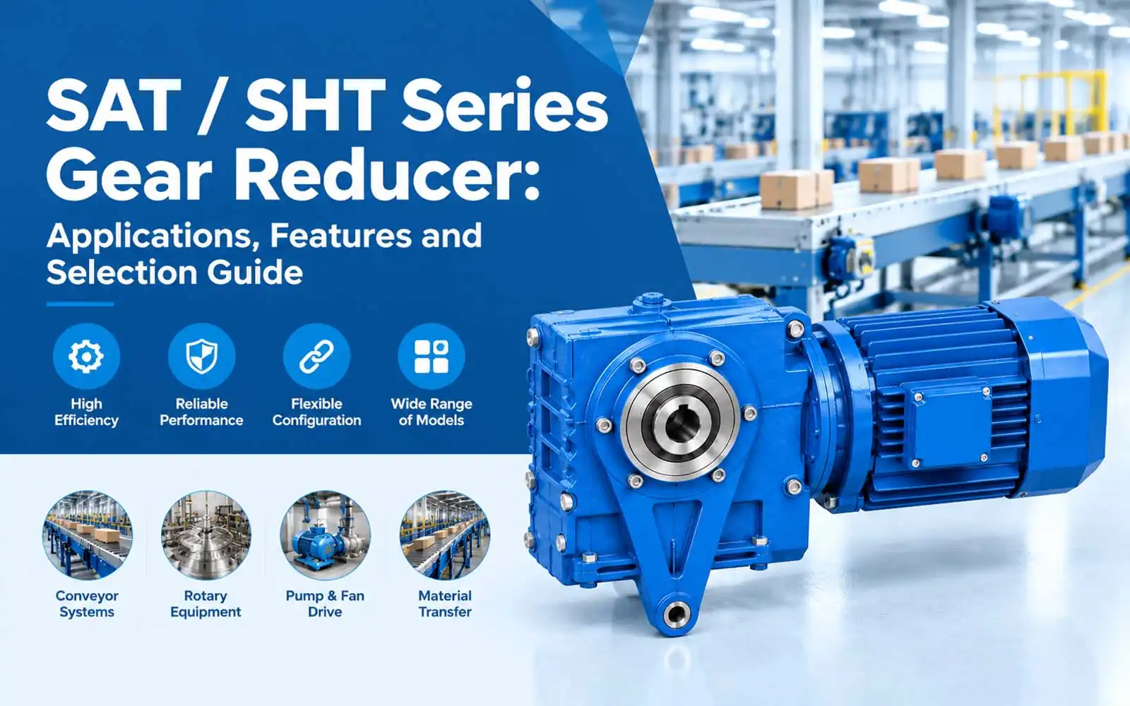
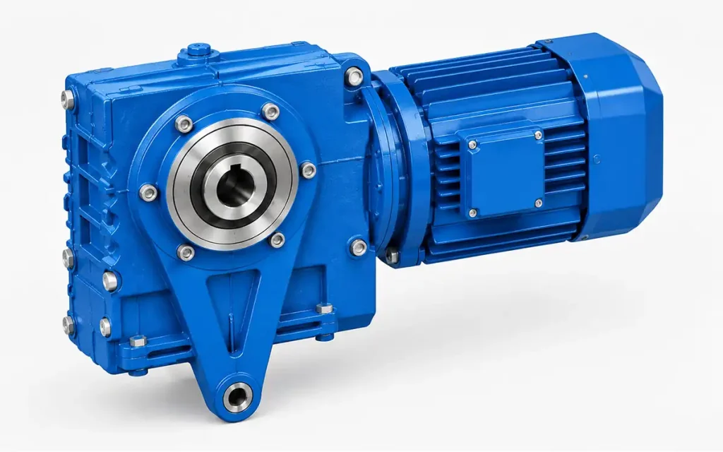
The SAT/SHT Series Gear Reducer is based on a Hollow Shaft + Torque Arm Arrangement. The gearbox connects to the equipment drive shaft through a hollow shaft, with a torque arm used as part of the mounting arrangement.
SAT37–SAT100 and SHT37–SHT100 follow the same basic mounting concept, while overall dimensions, shaft dimensions, and installation dimensions vary by model size.
1. Why Do Industrial Machines Need a Gear Reducer?
Industrial equipment may require an operating speed different from the speed supplied by the drive source. A gear reducer forms part of the mechanical transmission system between the drive and the connected equipment.
1.1 Drive Speed and Equipment Operation
The speed supplied by the drive source may not match the operating speed required by the equipment.
A gear reducer reduces the input speed to provide the required equipment speed.
Drive Speed → Speed Reduction → Required Equipment Speed
1.2 Basic Mechanical Power Transmission
A basic mechanical transmission path can be expressed as:
Drive Source → Gear Reducer → Driven Equipment
Power enters the gear reducer from the drive source and is transmitted at reduced speed to the driven equipment through the shaft connection.
1.3 Equipment Drive Requirements
Gear reducer selection and installation are based on factors such as:
- Drive source
- Required operating speed
- Reduction ratio
- Driven shaft dimensions
- Shaft connection
- Mounting position
- Equipment layout
- Installation conditions
These factors provide the basis for selecting a SAT or SHT gear reducer for the equipment drive system.
2. SAT / SHT Series Gear Reducer Features and Technical Characteristics
The SAT/SHT Series follows a shaft-mounted transmission arrangement.
Drive Source → SAT/SHT Gear Reducer → Hollow Shaft Connection → Driven Shaft → Equipment
Its installation structure also includes a connection between the gearbox and the equipment support structure.
Gear Reducer → Torque Arm Arrangement → Equipment Support Structure
2.1 SAT / SHT Hollow Shaft Structure
The SAT/SHT gear reducer uses a hollow shaft for connection to the driven shaft.
This shaft-mounted arrangement forms part of the mechanical transmission path between the gearbox and the equipment.
Key elements include:
- Hollow shaft
- Driven shaft connection
- Shaft-mounted installation
- Mechanical transmission
- Equipment drive layout
2.2 Driven Shaft Connection
The driven shaft is connected to the gearbox through the shaft-mounted interface according to the equipment arrangement.
Key installation details include:
- Shaft dimensions
- Hollow shaft dimensions
- Driven shaft position
- Connection position
- Equipment shaft arrangement
Gear Reducer → Hollow Shaft → Driven Shaft
The shaft connection is reviewed against the equipment dimensions and installation layout during installation planning.
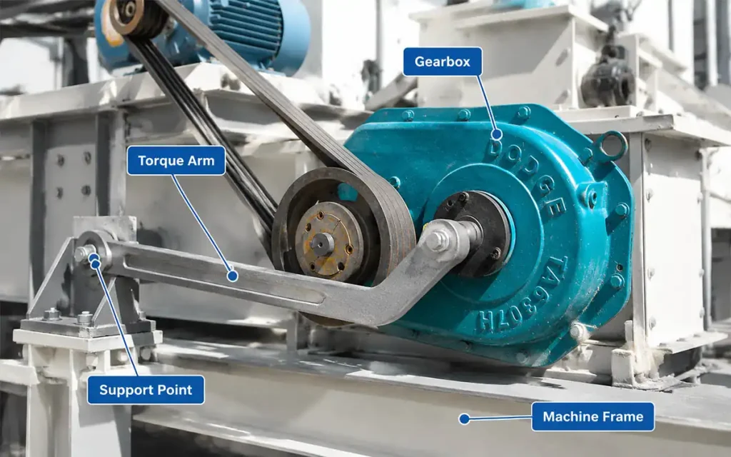
2.3 Torque Arm Arrangement
The torque arm forms part of the SAT/SHT mounting arrangement and connects the gearbox with the equipment support structure.
Key considerations include:
- Torque arm
- Equipment support structure
- Mounting position
- Installation arrangement
- Equipment structure
Gear Reducer → Torque Arm → Equipment Support Structure
Its position should suit the available installation space and equipment structure.
2.4 Speed Reduction and Equipment Drive
The SAT/SHT gear reducer forms part of the mechanical transmission path between the drive source and the driven equipment.
Power enters the gearbox from the drive source and leaves the gearbox at reduced speed through the connected shaft.
Drive Source → Gear Reducer → Connected Shaft → Driven Equipment
The operating speed of the driven equipment determines the required output speed.
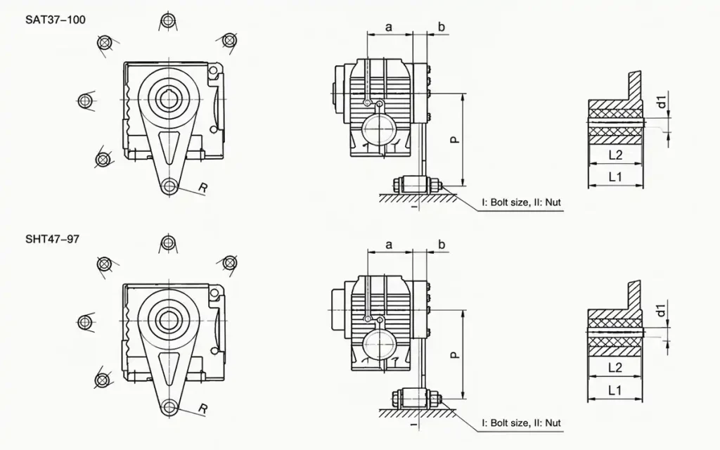
2.5 SAT / SHT Model Sizes and Dimensions
The SAT37–SAT100 and SHT37–SHT100 models follow the same basic mounting concept, while dimensions vary by model size.
Model selection is based on:
- Equipment dimensions
- Shaft dimensions
- Mounting position
- Support structure
- Available installation space
The selected model should suit the equipment dimensions and installation layout.
2.6 Equipment Installation Layout
The installation layout determines the position of the gearbox in relation to the driven shaft and equipment support structure.
Key factors include:
- Gearbox position
- Driven shaft position
- Torque arm position
- Equipment support structure
- Installation space
The position of these components should align with the overall equipment layout.
2.7 Technical Drawing Review
Technical drawings can be reviewed before installation to confirm:
- Overall dimensions
- Hollow shaft dimensions
- Driven shaft dimensions
- Torque arm dimensions
- Mounting position
- Equipment support position
- Available installation space
This review helps confirm dimensional compatibility before installation.
3. Why Choose a SAT / SHT Gear Reducer?
SAT/SHT gear reducers are suitable for equipment drive systems that use a shaft-mounted gearbox arrangement and require the gearbox position to fit the machine structure.
3.1 Supports Shaft-Mounted Equipment Integration
SAT/SHT gear reducers can be integrated into equipment drive systems where the gearbox connects directly to the driven shaft.
This arrangement can form part of the mechanical power path within an individual machine drive section.
Key factors include:
- Driven shaft
- Shaft-mounted connection
- Machine drive section
- Mechanical power path
- Equipment integration
The gearbox position and shaft connection should align with the overall drive system.
3.2 Supports Torque Arm Installation Arrangements
The mounting arrangement can be planned according to the gearbox position and the available support structure on the equipment.
Key installation factors include:
- Support point
- Support connection position
- Mounting structure
- Installation space
- Gearbox position
The mounting arrangement should suit the physical structure and available space of the equipment.
3.3 Suits Continuous and Repeated Equipment Operation
SAT/SHT gear reducers can be used in equipment operating continuously or through repeated mechanical cycles, according to application requirements.
Typical equipment functions include:
- Conveying
- Material transfer
- Feeding
- Production processes
The drive arrangement can be selected according to the operating requirements of the connected equipment.
3.4 Fits Different Equipment Layouts
Equipment layouts may differ in shaft position, gearbox position, support structure, and available mounting space.
Key factors include:
- Shaft position
- Gearbox position
- Mounting arrangement
- Available space
- Equipment geometry
The equipment layout determines the position of the gearbox, shaft connection, support structure, and related transmission components within the drive system.
4. SAT / SHT Gear Reducer Applications
The SAT / SHT Series can be used in equipment drive systems where the shaft-mounted connection and installation arrangement fit the machine structure.
Typical applications include conveying, material handling, feeding, production equipment, processing machinery, and rotary equipment.
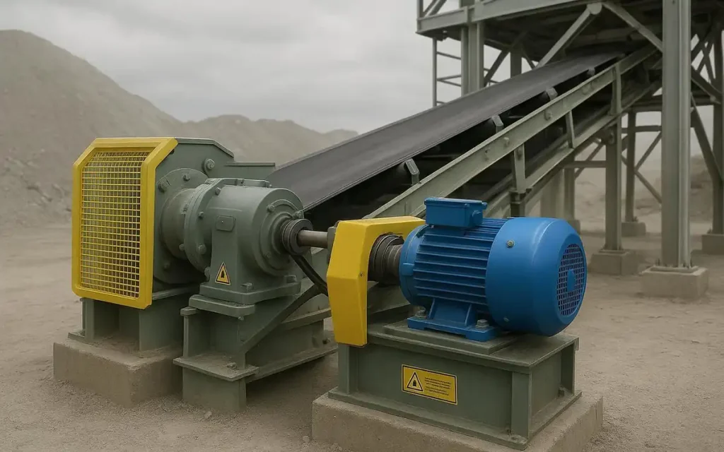
4.1 SAT / SHT Gear Reducers for Conveyor Systems
SAT / SHT gear reducers can be used in conveyor drive systems, including:
- Belt conveyors
- Roller conveyors
- Chain conveyors
A typical transmission path is:
Drive Source → SAT/SHT Gear Reducer → Hollow Shaft → Conveyor Shaft → Conveyor Drive
Key factors include the conveyor shaft connection, gearbox position, mounting arrangement, and available installation space.
4.2 Material Handling and Transfer Equipment
Material handling and transfer equipment may use mechanical drive systems for repeated movement between equipment sections.
Typical examples include:
- Material transfer units
- Transfer mechanisms
- Handling equipment
SAT / SHT gear reducers can form part of the transmission system between the drive source and the transfer mechanism. The shaft connection and installation layout should align with the mechanical arrangement of the equipment.
4.3 Feeding Equipment
SAT / SHT gear reducers can be used in shaft-driven feeding systems.
Typical applications include:
- Automatic feeders
- Conveyor feeding systems
- Material feeding equipment
The gearbox can be incorporated into the feeding drive according to the required operating speed, shaft connection, and equipment layout.
4.4 Production Line Drive Sections
Production lines may contain individual drive sections for assembly, conveying, or material transfer.
Typical applications include:
- Production line drive sections
- Assembly equipment
- Material transfer sections
The gearbox can be incorporated into individual drive sections where the shaft connection and installation position suit the machine structure.
4.5 Processing Equipment
SAT / SHT gear reducers can be incorporated into the mechanical drive systems of processing equipment.
Typical applications include:
- Material processing machines
- Industrial processing equipment
- Manufacturing machine drives
Model selection is based on the required operating speed, shaft dimensions, mounting structure, and installation arrangement.
4.6 Rotary and General Industrial Equipment
SAT / SHT gear reducers can also be used in shaft-driven rotary equipment and general industrial machinery.
Typical applications include:
- Rotary equipment
- General industrial machinery
- Shaft-driven machine sections
Required operating speed, reduction ratio, shaft dimensions, mounting position, and available installation space are reviewed during model selection.
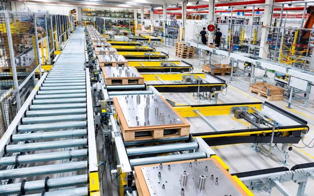
5. How to Select the Right SAT / SHT Gear Reducer?
Model selection is based on the equipment speed, shaft connection, mounting arrangement, and available installation space.
Speed Requirements
Confirm the input speed and required equipment speed to determine the reduction ratio.
Shaft Connection
Review the driven shaft dimensions and gearbox connection arrangement in relation to the equipment structure.
Mounting Arrangement
Confirm the gearbox position, support structure, and available space for installation.
Equipment Layout and Dimensions
SAT and SHT models use the same basic installation concept, while dimensions vary by model size. The selected model should suit the equipment layout and fit within the available installation space.
Information for Model Selection
For equipment and OEM projects, provide the required operating speed, reduction ratio, driven shaft dimensions, connection arrangement, mounting layout, and installation dimensions.
The final SAT or SHT model should be selected according to the equipment connection and installation requirements.
6. FAQ
Q1: What type of gearbox is the SAT / SHT Series?
It is a hollow-shaft gear reducer with a torque arm installation arrangement.
Q2: What is a hollow shaft gear reducer used for?
It connects the gear reducer directly to a driven shaft through the hollow shaft.
Q3: Can SAT / SHT gear reducers be used for conveyor systems?
Yes. They can be used for belt, roller, and chain conveyor drives.
Q4: What is the purpose of the torque arm arrangement?
It supports the gearbox installation by connecting it with the equipment support structure.
Q5: What equipment can use SAT / SHT gear reducers?
Typical applications include conveying, material handling, feeding, processing, and rotary equipment.
Q6: What information is needed for model selection?
Confirm the input speed, required operating speed, reduction ratio, shaft dimensions, and installation layout.
Q7: Should hollow shaft dimensions be checked before installation?
Yes. They need to be checked against the driven shaft and connection arrangement.
Q8: Can technical drawings be reviewed before ordering?
Yes. Drawings can be used to check dimensions, shaft connections, torque arm positions, and installation space.
7. Conclusion
Send us your equipment details or installation drawing for a SAT / SHT gear reducer review.
Our technical team can review the required operating speed, reduction ratio, shaft connection, mounting arrangement, gearbox dimensions, and installation requirements.
This information can support SAT / SHT model selection for equipment and OEM projects.


