 +86 184 3796 0706
 info@destinytrans.com


Introduction
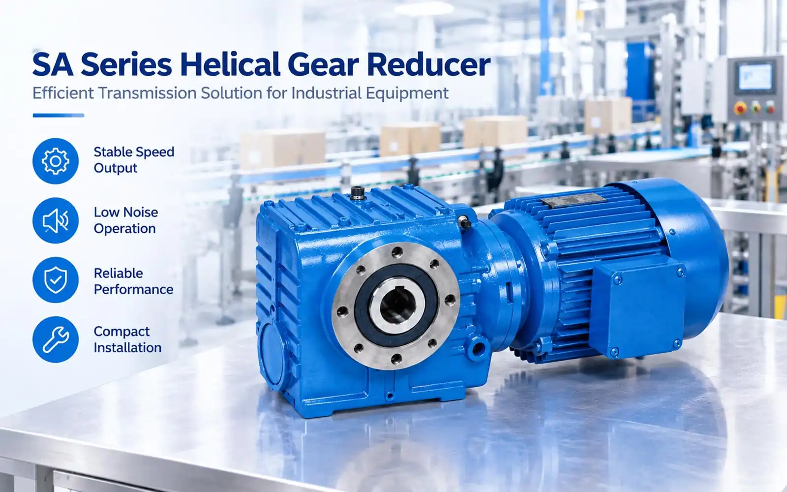
Industrial equipment often needs to reduce motor speed before driving conveyors, feeding systems, packaging machines, or production lines. The gearbox helps match motor speed with the working speed required by the machine.
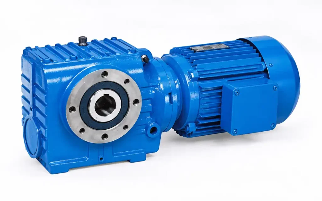
The SA Series Gear Reducer is designed for industrial drive systems where speed reduction, practical machine layout, and motor matching are required. It can be applied in conveyor, material handling, packaging, and production equipment.
CAD drawing support is available for installation checks, while motor matching and OEM configuration can be discussed according to machine requirements.
1. Why Do Industrial Machines Need a Gear Reducer?
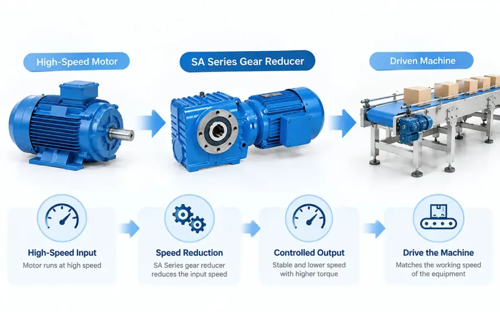
Industrial motors often run faster than the driven equipment requires. A gear reducer lowers the motor speed and provides an output speed that matches the machine.
It helps to:
- Match motor speed with machine requirements
- Reduce input speed
- Set the required output speed
- Connect the motor with driven equipment
Gear reducers are commonly used in conveyors, feeding systems, packaging equipment, and production lines where the motor needs to work at a different speed from the machine.
The SA Series Gear Reducer is designed for industrial equipment that requires speed reduction and practical mechanical drive arrangements.
2. SA Series Gear Reducer Features and Technical Advantages
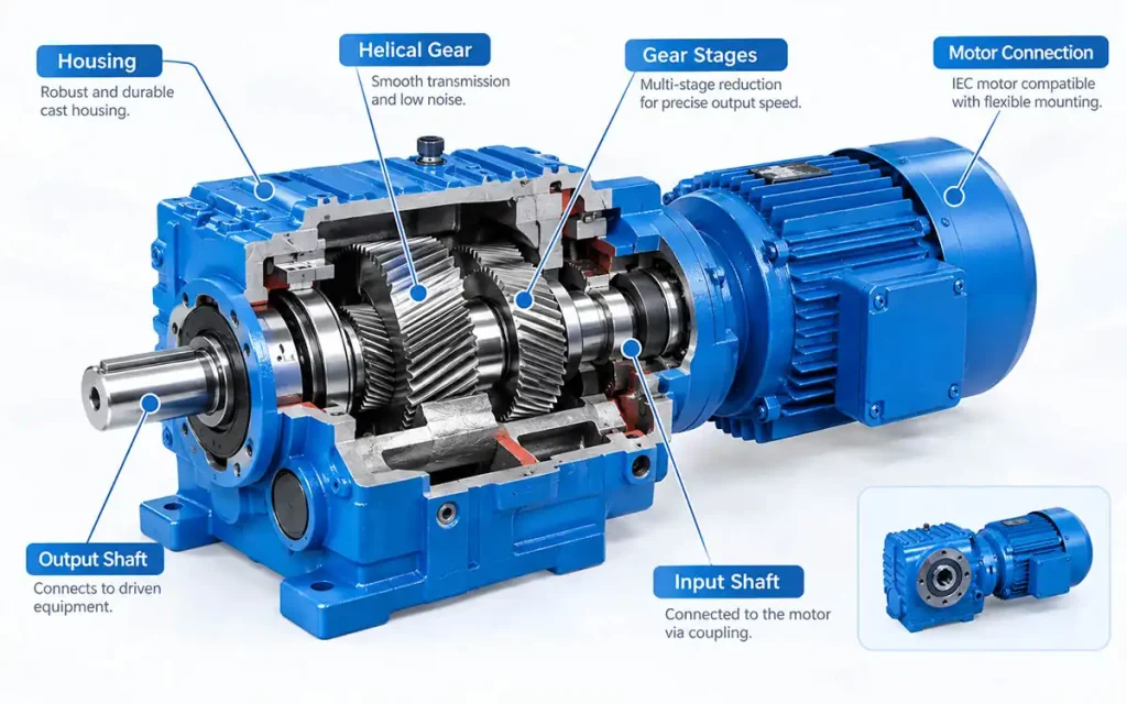
The SA Series is designed for industrial equipment requiring speed reduction and a mechanical drive arrangement. Specific dimensions and configurations depend on the selected model.
|
Item |
Specification |
|
Model |
SA Series |
|
Gear Type |
Helical Gear Reducer |
|
Drive Arrangement |
Based on Selected Model |
|
Mounting Type |
Based on Selected Model |
|
Output Type |
Based on Selected Model |
|
Reduction Ratio |
Available Various Ratios |
|
Motor Connection |
Based on Selected Model |
|
Application |
Industrial Equipment |
Note: Housing dimensions, bore or shaft sizes, mounting details, and motor configurations should be confirmed with the selected SA model and technical drawing.
2.1 Reduction Ratio
The reduction ratio determines how much the motor speed is reduced before reaching the driven equipment. The required ratio depends on the machine’s working speed, such as:
- Conveyor speed
- Feeding speed
- Production cycle
- Machine movement
The selected ratio should match the motor speed and required output speed.
2.2 Helical Gear Arrangement
The SA Series uses a helical gear arrangement for speed reduction. Different configurations and ratios are available according to the required output speed.
Key characteristics include:
- Helical gear arrangement
- Reduction stages
- Available ratios
- Mechanical drive configuration
2.3 Mounting and Output Configuration
Different SA models are available with different housing sizes, bore dimensions, and mounting configurations. The exact output and mounting dimensions should be checked against the selected model drawing.
This allows customers to confirm the gearbox connection with the driven equipment before ordering.
2.4 Motor Connection
Motor matching depends on the selected SA model. Key points include:
- Motor frame size
- Motor dimensions
- Flange connection
- Motor matching
The motor specification should be confirmed together with the gearbox model.
2.5 CAD Drawing and Installation Support
CAD drawings can help customers check the gearbox dimensions, bore or shaft connection, motor size, and available installation space before ordering.
This is useful for confirming the gearbox position and connection with the machine layout.
3. Why Choose SA Series Gear Reducer?
The SA Series is intended for equipment where motor speed, machine layout, and working cycles need to match. Its value is mainly seen in machine design and equipment selection.
3.1 Helps Match the Machine Working Pace
The selected SA configuration can bring motor speed in line with the working pace of the driven equipment. This is useful when a machine has a defined feeding rate, conveyor speed, production cycle, or movement interval.
3.2 Practical for Different Machine Layouts
For OEM equipment builders, gearbox placement needs to fit the available space and overall machine design. The SA Series can be selected according to the motor position, output connection, mounting arrangement, and installation space.
This gives machine designers more flexibility when arranging the drive components.
3.3 Fits Repeated Mechanical Movement
Industrial equipment often follows the same working sequence throughout a production cycle. The SA Series can support these repeated movements where the gearbox needs to follow a defined production rhythm and machine cycle.
3.4 Available in Different Sizes
Different SA models are available with different housing sizes, bore or shaft dimensions, and motor frame options. The final model should be selected according to the machine speed, motor, connection dimensions, and installation requirements.
4. SA Series Applications in Different Industries
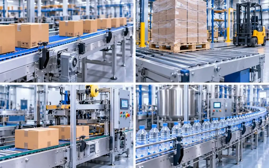
The SA Series is used in industrial equipment where motor speed needs to match the working requirements of the driven machine. Its application range includes conveying, material handling, packaging, production, and other mechanical drive systems.
4.1 Conveyor Systems
The SA Series can serve as an industrial conveyor gearbox for:
- Belt conveyors
- Roller conveyors
- Chain conveyors
In these systems, the gearbox drives the conveyor mechanism at the required working speed and connects the motor with the conveying equipment.
4.2 Material Handling Equipment
In material handling systems, the gearbox drives equipment used for moving or feeding materials. Common applications include:
- Pallet conveyors
- Feeding systems
- Logistics equipment
The SA Series can serve as a material handling gearbox when the motor, output connection, and installation arrangement match the equipment.
4.3 Packaging Machinery
Packaging equipment often includes conveying, feeding, and sorting mechanisms. Typical applications include:
- Carton conveyors
- Packing equipment
- Sorting equipment
For these machines, the SA Series can provide the gearbox drive for packaging machine mechanisms that require a defined working speed.
4.4 Production Line Equipment
Typical drive points include:
- Assembly lines
- Feeding equipment
- Processing lines
The gearbox helps match motor speed with the machine cycle while fitting the available equipment layout, making it an option for production line gearbox applications.
4.5 Mixing & Processing Equipment
Mixers and processing machines may require a gearbox for rotary movement and speed adjustment. Common equipment includes:
- Mixers
- Agitators
- Processing machines
The SA Series may be considered for these applications based on the required speed, load, shaft connection, and working conditions.
4.6 Food Processing Equipment
In food processing equipment, common drive points include:
- Food conveyors
- Feeding machines
- Processing equipment
The SA Series can be used for conveying, feeding, and other mechanical drive points where the selected configuration matches the equipment requirements.
4.7 Automation Equipment
For automated equipment, the gearbox can support assembly and material-feeding movements within the machine layout. Typical applications include:
- Assembly equipment
- Material feeding systems
This makes the SA Series an option for selected automation gearbox applications.
4.8 Textile & Printing Equipment
Textile and printing machines may also use gearboxes for feeding and rotary mechanisms. These are secondary applications and should be evaluated according to the machine speed, connection dimensions, and installation conditions.
5. How to Select the Right SA Series Gear Reducer?
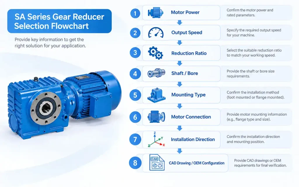
Before selecting an SA Series gearbox, customers should confirm the motor power, required output speed, reduction ratio, shaft or bore size, and mounting conditions. These details help determine the appropriate model and configuration.
Motor Power
Start with the motor power and input conditions. The gearbox should match the motor used by the machine.
Output Speed
The required output speed depends on the machine’s working process. For example, conveyors, feeding equipment, and production lines may each require a different working speed.
Reduction Ratio
The reduction ratio is selected according to the motor speed and the required gearbox output speed. The correct ratio should be confirmed before choosing the model.
Shaft / Bore Size
Check the gearbox output connection against the driven equipment. Shaft or bore dimensions need to match the machine connection to avoid installation problems.
Mounting Type
The mounting method should match the equipment design and available space. Customers should confirm the mounting position and installation dimensions from the selected model drawing.
Motor Connection
Motor connection is separate from motor power. The selection should confirm the motor frame size, flange dimensions, and motor configuration required for the gearbox.
Installation Direction
The machine layout should also be checked for horizontal or vertical installation. The selected SA model must match the intended mounting direction.
CAD Drawing Support
CAD drawings can help customers check the overall gearbox size, shaft or bore dimensions, motor dimensions, mounting space, and equipment connection before ordering.
OEM Support
For OEM projects, the SA Series configuration can be discussed according to the motor, shaft or bore, mounting method, and machine requirements. This allows the gearbox model to be selected around the actual equipment design.
6. FAQ
Q1. What type of gearbox is SA Series?
The SA Series is a helical gear reducer designed for industrial drive applications.
Q2. What is SA Series gearbox used for?
It is used for equipment such as conveyors, material handling systems, packaging machines, and production equipment.
Q3. Can SA Series gearbox be used for conveyor systems?
Yes. It can be used for belt, roller, and chain conveyor drives when the required speed and mounting conditions match.
Q4. What industries use SA Series gearboxes?
Common applications include material handling, packaging, production lines, processing, and food processing.
Q5. What equipment can use an SA Series gearbox?
The SA Series can be used for conveyors, feeding systems, packaging equipment, processing machines, and mixing equipment.
Q6. What motor sizes are available for SA Series?
Motor frame size and connection dimensions depend on the selected SA model and should be confirmed from the relevant technical drawing.
Q7. Can SA Series gearbox be customized?
Yes. OEM configuration can be discussed based on the motor, shaft or bore, mounting, and machine requirements.
Q8. What information is needed to select an SA Series gearbox?
Customers should provide motor power, output speed, reduction ratio, shaft or bore size, mounting details, and installation dimensions.
7. Conclusion
If you are selecting a gear reducer for conveyors, material handling, packaging, production, or processing equipment, send us your motor data, required output speed, and installation dimensions. These details help our team check the appropriate SA Series configuration for your machine.
We can also provide CAD drawings, motor matching support, and OEM configuration for projects with specific mounting or connection requirements. Send us your equipment details, and our engineering team can recommend an SA Series gearbox based on your application and installation conditions.


