 +86 184 3796 0706
 info@destinytrans.com


Introduction
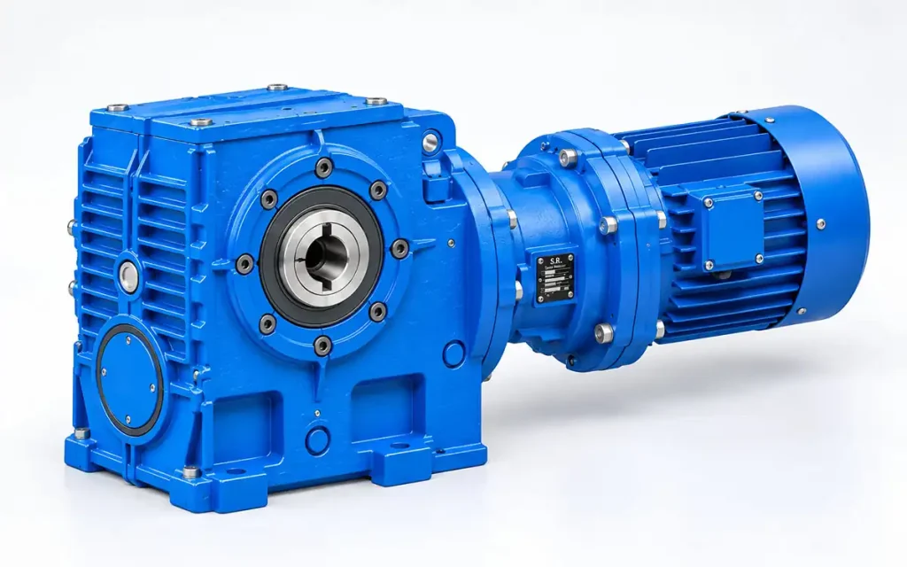
The S..R.. Series Gear Reducer combines S Series and R Series gear units in one transmission arrangement for industrial speed-reduction applications. Typical uses include conveying, material handling, lifting, mixing, and packaging or feeding equipment.
Drive Source → S..R.. Gear Reducer → Driven Equipment
1. Why Do Industrial Machines Need a Gear Reducer?
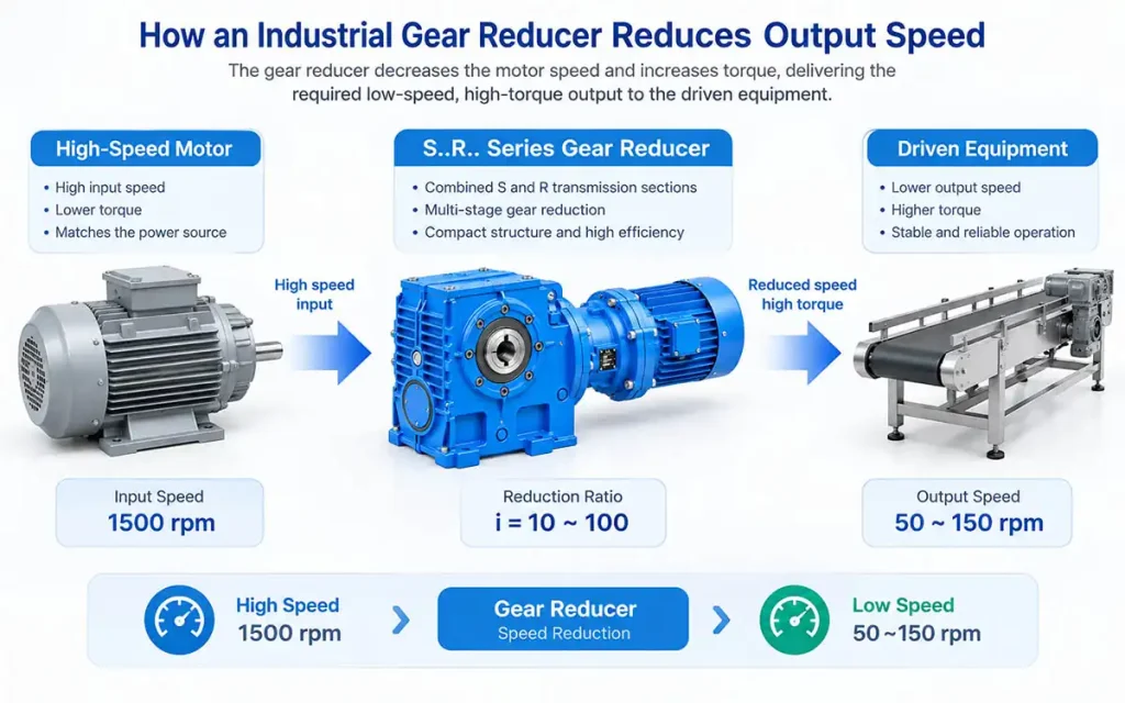
Industrial motors often run at a higher speed than the machine requires. A gear reducer brings the speed down and transfers mechanical power to the driven equipment.
1.1 Motor Speed and Machine Operating Speed
The motor speed may not match the machine’s required operating speed. Gear reduction allows the drive to reach the desired output speed.
1.2 Speed Reduction and Power Transmission
The gear train reduces rotational speed while transferring power from the motor to the machine.
1.3 Why Combined Gear Transmission Matters
The required reduction level depends on the machine’s operating speed and drive arrangement. Combining S and R sections places the required reduction stages within one drive unit.
2. S..R.. Series Gear Reducer Features and Technical Characteristics
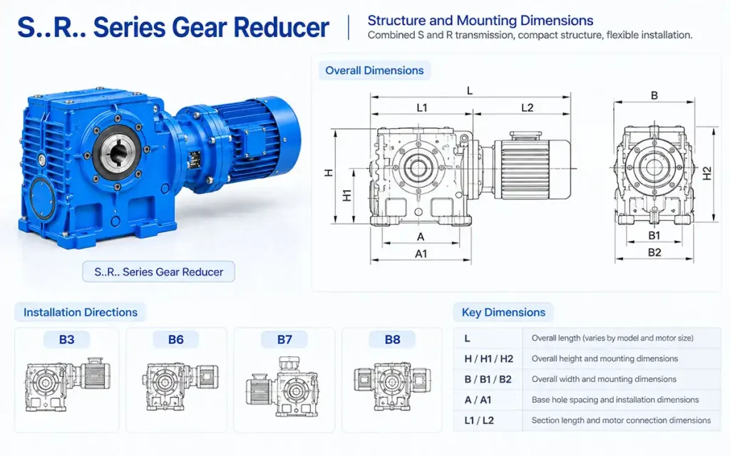
The S..R.. Series combines Series S and Series R in one geared unit. The technical drawing shows a consistent basic arrangement, with dimensions changing according to the selected model and motor size.
2.1 S and R Series Combined Transmission
S..R.. denotes a combined type of Series S and Series R, forming a combined transmission arrangement for speed reduction.
2.2 Combined Gear Arrangement
The two gear sections form one transmission path between the motor and driven equipment, with the selected combination determining the overall reduction arrangement.
2.3 Housing and Overall Arrangement
The S..R.. models share a similar external arrangement. The main dimensional differences are related to the selected model and motor combination.
2.4 Model and Size Range
The technical drawing lists S..R.. models including S..37R17, S..47R17, S..57R17, S..67R37, S..77R37, S..87R57, S..97R57, and S..100R77.
2.5 Motor Frame Matching
The drawing specifies different motor frame sizes for each model, together with the corresponding L dimension. These values should be checked when matching the motor and planning the installation space.
2.6 Mounting Dimensional Drawing
The S..R.. Mounting Dimensional Description provides the reference for model selection, motor matching, overall dimensions, and installation planning.
3. How S..R.. Integrates with Industrial Equipment
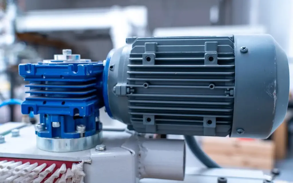
The S..R.. Series sits between the motor and driven equipment, with installation dimensions matched to the selected model and motor size.
3.1 Drive Source and Motor Connection
The motor frame size and connection arrangement should match the selected S..R.. unit. Motor position and overall length should also be considered during equipment layout.
3.2 Reducer and Machine Drive Arrangement
Between the motor and machine-side drive, the S..R.. unit provides the required speed reduction and power transmission. Its installation position depends on the layout of the driven equipment.
3.3 Installation Position and Equipment Layout
Available space around the drive should be considered before installation, including the reducer position, motor position, overall length, and required clearance.
3.4 Motor Frame and Dimensional Verification
The selected motor frame and overall length should be checked against the equipment layout. The L dimension shown in the technical drawing helps confirm the required installation space for each model and motor combination.
4. S..R.. Series Gear Reducer Applications
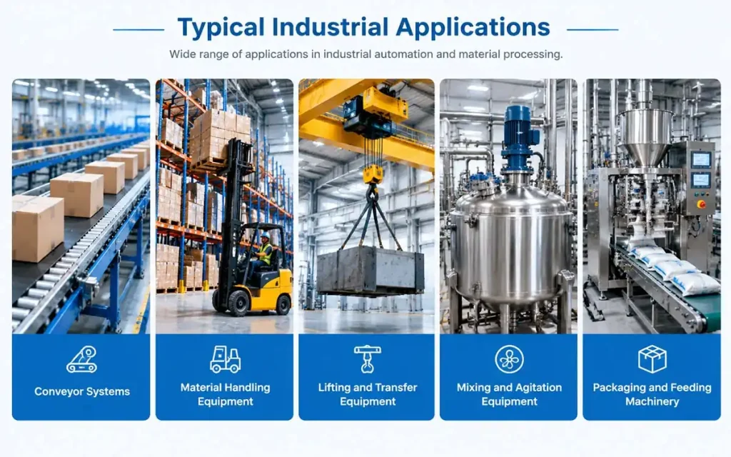
Typical applications for the S..R.. Series include conveying, material handling, lifting, mixing, and packaging or feeding equipment.
4.1 Conveyor Systems
Belt conveyors and chain conveyors can use the S..R.. for reduced-speed drive transmission in conveying systems.
4.2 Material Handling Equipment
Material transfer equipment and transfer units often require reduced-speed drive transmission for controlled material movement.
4.3 Lifting and Transfer Equipment
Lifting mechanisms and transfer mechanisms may use the S..R.. where the required output speed, reduction ratio, and installation conditions match the selected model.
4.4 Mixing and Agitation Equipment
Industrial mixers and agitators can incorporate the S..R.. for low-speed rotational drive applications.
4.5 Packaging and Feeding Machinery
Packaging machinery and feeding equipment may use the S..R.. for reduced-speed drive applications where the installation arrangement is suitable.
5. How to Select the Right S..R.. Series Gear Reducer?
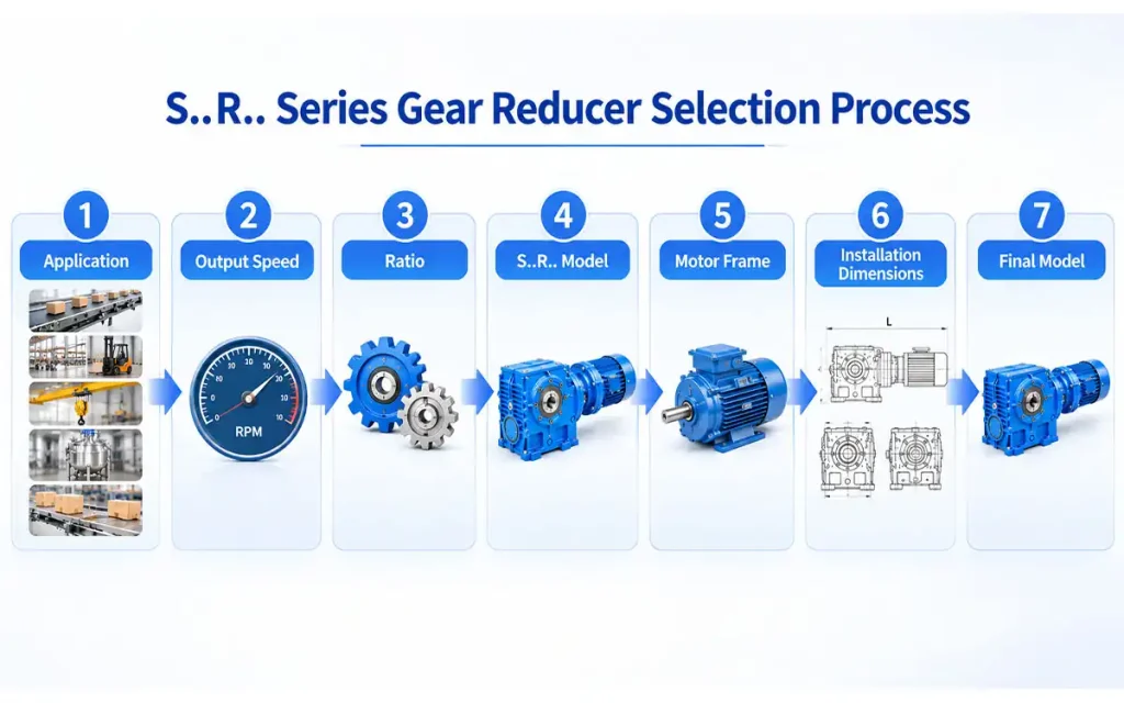
A practical selection path is:
Application → Output Speed → Ratio → S..R.. Model → Motor Frame → Installation Dimensions → Final Model
Step 1. Determine the Application
Start with the equipment type, such as a conveyor, material handling unit, lifting or transfer mechanism, mixer, or feeding machine.
Step 2. Determine Required Output Speed
Identify the machine’s required operating speed and the corresponding reducer output speed.
Step 3. Determine the Reduction Ratio
Use the input and required output speeds to calculate the ratio:
Reduction Ratio = Input Speed ÷ Required Output Speed
Step 4. Select the S..R.. Model
Select the S..R.. model based on the required ratio and output speed, then confirm the motor and equipment requirements.
Step 5. Confirm the Motor Frame Size
Check the motor frame size, motor connection, and overall length for the selected combination.
Step 6. Check Installation Dimensions
Review the overall dimensions, mounting position, motor position, and available clearance against the equipment layout.
Step 7. Confirm the Technical Drawing
Refer to the S..R.. Mounting Dimensional Description for the final model and dimensional check before ordering.
6. FAQ
Q1: What is an S..R.. Series Gear Reducer?
It is a combined gear reducer consisting of Series S and Series R transmission sections.
Q2: What does S..R.. mean?
S..R.. indicates a combined type of Series S and Series R.
Q3: What equipment can use an S..R.. Gear Reducer?
Typical applications include conveyor systems, material handling equipment, lifting and transfer mechanisms, mixing equipment, and packaging or feeding machinery.
Q4: Can the S..R.. be used for conveyor systems?
Yes. It may be used for belt conveyors and chain conveyors when the required speed, ratio, and installation conditions are suitable.
Q5: What should be checked when selecting an S..R.. model?
Check the output speed, reduction ratio, motor frame, installation dimensions, and equipment layout.
Q6: What dimensions should be confirmed before ordering?
Confirm the motor frame size, overall length, mounting dimensions, and available installation space.
7. Conclusion
Need an S..R.. Series Gear Reducer for your equipment? Send us your required output speed, reduction ratio, motor requirements, and installation dimensions. We can help confirm a suitable S..R.. model and the corresponding dimensional details before ordering.


