 +86 184 3796 0706
 info@destinytrans.com


Introduction
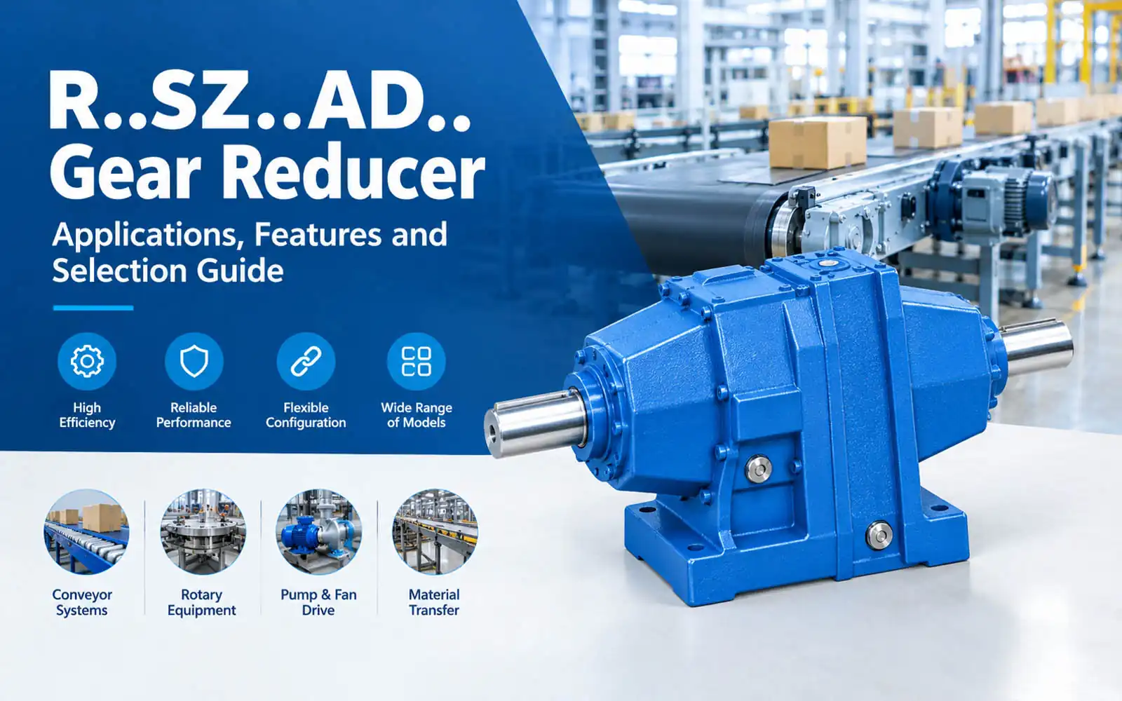
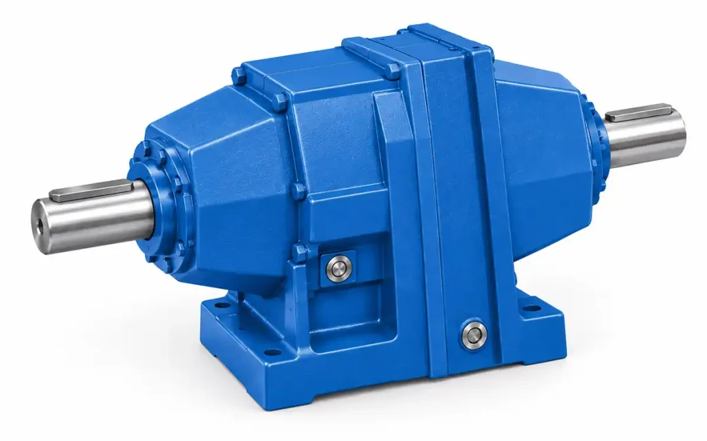
The R..SZ..AD.. Series Gear Reducer is an R Series helical gear reducer with an input shaft connection for external drive systems. The AD configuration is available in different sizes, with mounting and shaft dimensions varying by model.
External Drive → Input Shaft → R..SZ..AD.. Gear Reducer → Driven Equipment
It can be used in conveyor systems, rotary equipment, and pump or fan drive applications.
1. Why Do Industrial Machines Need a Gear Reducer?
Industrial drive systems often run at a higher speed than the machine requires. A gear reducer lowers the speed and transfers the required mechanical power to the driven equipment.
1.1 Motor or External Drive Speed
The drive source and machine may require different operating speeds. The reducer brings the input speed down to the level required by the machine.
1.2 Speed Reduction and Power Transmission
Besides reducing speed, the gear unit transfers mechanical power to the machine-side drive.
1.3 Input Shaft Drive Arrangement
The AD configuration receives mechanical input through an external input shaft rather than a direct motor connection.
2. R..SZ..AD.. Gear Reducer Features and Technical Characteristics
The R..SZ..AD.. is an R Series helical gear reducer with an input shaft configuration. Its main structural details are the gear unit, input shaft, and model-specific dimensions.
2.1 Helical Gear Reducer Structure
The R..SZ..AD.. uses a helical gear transmission to reduce speed and transfer mechanical power to the driven equipment.
2.2 Input Shaft Type
The AD configuration uses an input shaft for mechanical connection to an external drive.
2.3 SZ..AD.. Configuration
R..SZ..AD.. identifies this input-shaft configuration within the R Series. The basic arrangement remains consistent, while shaft and mounting dimensions vary by model.
2.4 Model Range and Dimensional Variations
The dimensional drawings cover:
R.SZ37, R.SZ47, R.SZ57, R.SZ67, R.SZ77, R.SZ87, R.SZ97, R.SZ107, R.SZ137, R.SZ147, R.SZ167, and R.SZ177.
The basic external layout is consistent across the range, with dimensions changing according to model size.
2.5 Mounting and Input Shaft Dimensions
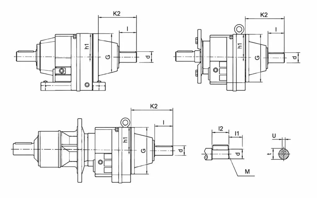
Model-specific dimensions include:
- Input shaft diameter and length
- Mounting dimensions
- Shaft connection dimensions
- Overall gearbox dimensions
Use the corresponding model drawing when matching the reducer to the equipment layout.
2.6 Technical Drawing Reference
The R..SZ..AD.. dimensional drawings provide model-specific input shaft, mounting, and overall dimensions. Use the relevant drawing when checking the selected model for equipment installation.
3. How R..SZ..AD.. Integrates with Industrial Equipment
The R..SZ..AD.. configuration connects the drive source through its input shaft and transfers the reduced-speed output to the machine-side drive.
3.1 External Drive and Input Shaft Connection
Connect the external drive to the AD input shaft according to the required drive arrangement. The connection must suit the shaft dimensions and transmission components.
3.2 Input Shaft Dimensions
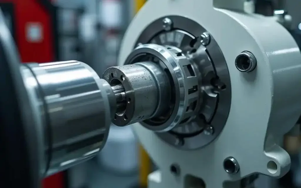
The input shaft diameter, length, and connection dimensions must suit the external drive or coupling.
3.3 Reducer and Machine-Side Connection
Connect the reducer output to the machine-side transmission according to the equipment layout. The shaft and mounting interface should suit the machine-side transmission.
3.4 Installation Space and Dimensional Check
Before installation, check the model-specific drawing for:
- Shaft position
- Mounting position
- Overall dimensions
- Required clearance
This helps confirm that the selected R..SZ..AD.. model fits the equipment layout.
4. R..SZ..AD.. Gear Reducer Applications
The R..SZ..AD.. Gear Reducer fits industrial equipment that uses a mechanical input shaft connection. Common application areas include conveying, rotary equipment, pump and fan drives, and material transfer.
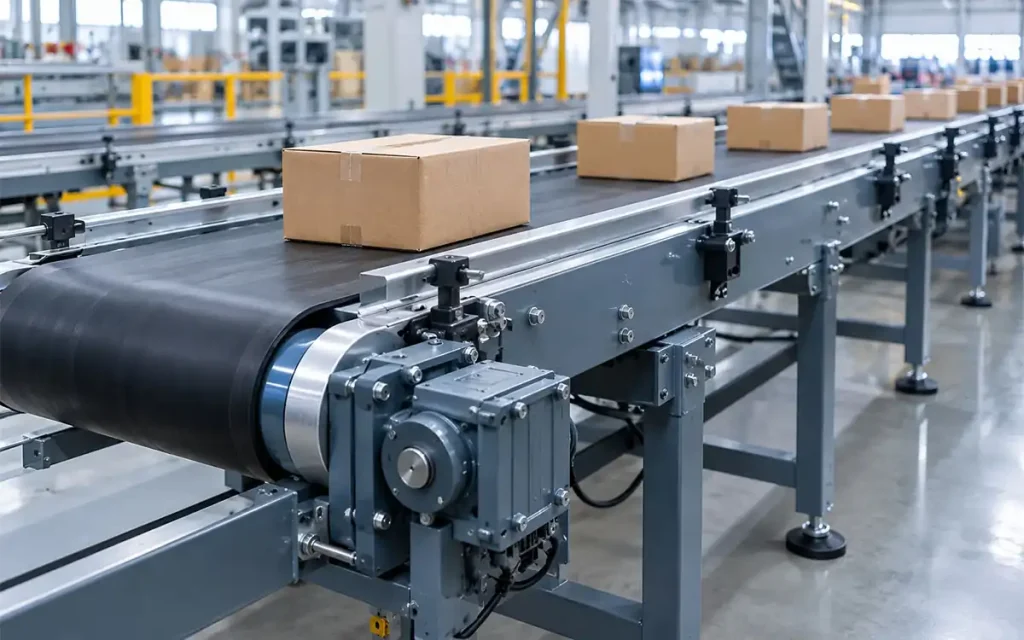
4.1 Conveyor Systems
The R..SZ..AD.. configuration can be used for:
- Roller Conveyors
- Belt Conveyors
- Chain Conveyors
4.2 Rotary Equipment
Rotary applications include:
- Rotary Tables
- Rotary Transfer Equipment
4.3 Pump and Fan Drive Equipment
Pump and fan drive applications include:
- Pump Drive Systems
- Fan Drive Equipment
4.4 Material Transfer Equipment
Material transfer equipment may include:
- Corner Transfer Units
- Material Transfer Systems
The suitable model depends on the required speed, shaft connection, and installation dimensions.
5. How to Select the Right R..SZ..AD.. Gear Reducer?
Use the following selection path:
Speed → Ratio → Model → Input Shaft → Output Connection → Installation Dimensions
Step 1. Determine Required Speed
Start with the input speed, required output speed, and reduction ratio.
Step 2. Select the Model
Choose the R..SZ..AD.. model according to the required ratio and output speed.
Step 3. Input Shaft
Review the input shaft diameter, shaft length, and connection dimensions against the external drive.
Step 4. Output Connection
Make sure the reducer output suits the driven equipment and transmission components.
Step 5. Installation Space
Allow for the reducer body, shaft arrangement, and mounting position within the available space.
Step 6. Technical Drawing
Refer to the relevant R..SZ..AD.. Mounting Dimensional Description for the final dimensional review before ordering.
6. FAQ
Q1: What is an R..SZ..AD.. Gear Reducer?
It is an R Series helical gear reducer with an input shaft configuration.
Q2: What does AD mean in the R..SZ..AD.. configuration?
AD indicates the input shaft type, allowing connection to an external drive.
Q3: How is the AD input shaft connected to the drive system?
The external drive connects directly to the reducer through the AD input shaft.
Q4: What models are available for the R..SZ..AD.. type?
Available sizes shown in the drawings range from R.SZ37 to R.SZ177.
Q5: What equipment can use an R..SZ..AD.. Gear Reducer?
It can be used for conveyors, rotary tables, pump drives, and fan drive equipment.
Q6: Can R..SZ..AD.. be used for conveyor systems?
Yes. It can be used with roller, belt, and chain conveyors.
Q7: What dimensions should be checked before selecting a model?
Check the input shaft, output connection, mounting, and overall dimensions.
7. Conclusion
Need an R..SZ..AD.. Gear Reducer for your equipment? Send us the required input and output speed, input shaft dimensions, output connection, and installation requirements. We can help you select a suitable model and confirm the dimensional details before ordering.


