 +86 184 3796 0706
 info@destinytrans.com


Introduction
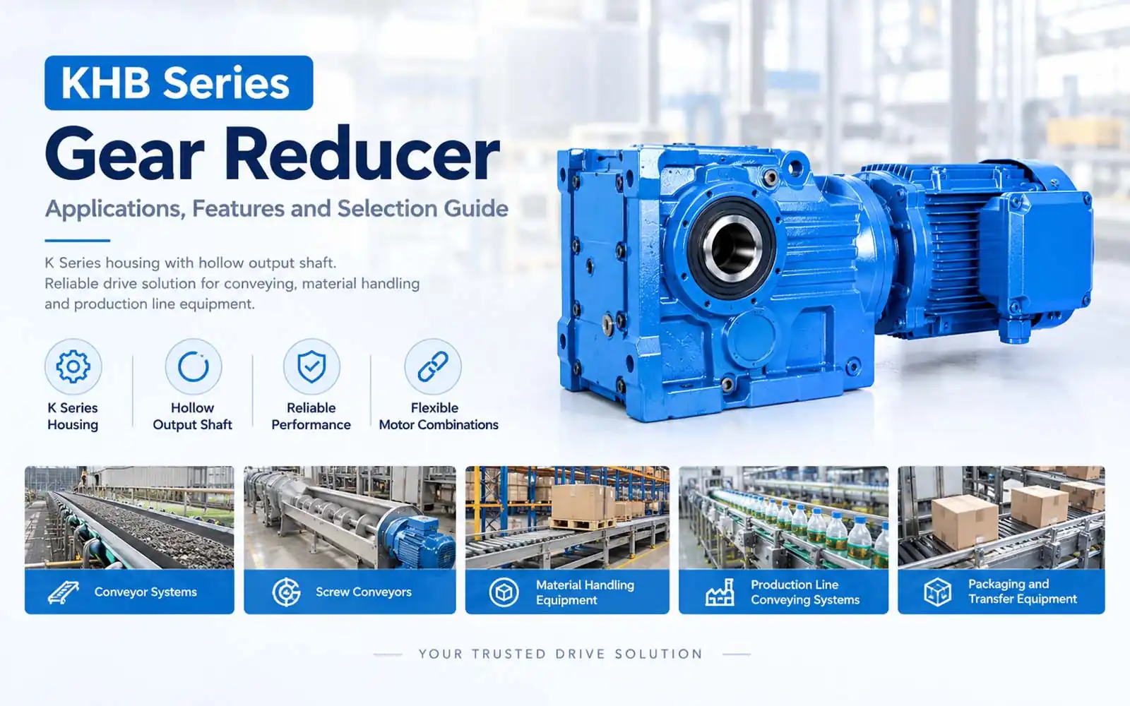
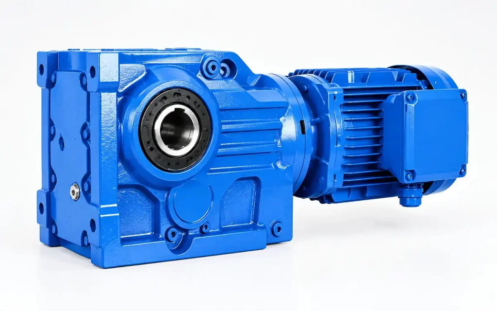
The KHB Series Gear Reducer uses a K Series housing with a hollow output shaft for direct connection to the driven equipment. The range covers KHB47–KHB107, with model dimensions and motor combinations varying by size. It is used in conveyor systems, screw conveyors, material handling equipment, and production-line conveying systems.
Motor → KHB Gear Reducer → Driven Equipment
1. Why Do Industrial Machines Need a Gear Reducer?
Industrial machines often require a lower operating speed than the motor provides. A gear reducer adjusts the motor speed before rotation reaches the driven mechanism.
1.1 Motor Speed and Machine Speed
Motor speed and machine operating speed are not always the same. For conveying and material-handling equipment, the required output speed depends on the machine design and conveying process.
1.2 Speed Reduction and Power Transmission
Speed reduction matches motor rotation to the required machine speed while transmitting rotation to the output side. For KHB applications, this creates a controlled-speed drive between the motor and equipment.
1.3 Gear Reducer and Machine-Side Drive
A machine with a driven shaft requires a suitable connection between the gearbox and the equipment. With its hollow output shaft, KHB can connect with a corresponding machine-side shaft, forming a direct mechanical link to the driven mechanism.
2. KHB Series Gear Reducer Features and Technical Characteristics
KHB follows the K Series housing design with a hollow output shaft. Across KHB47–KHB107, the basic arrangement remains consistent, while dimensions and motor combinations vary with model size.
2.1 K Series Housing Structure
KHB uses the K Series housing layout, with housing dimensions varying by frame size to suit different machine layouts.
2.2 Hollow Output Shaft
A hollow output shaft forms the main machine-side interface. It accommodates a corresponding driven shaft as part of the equipment drive arrangement.
2.3 KHB47–KHB107 Model Range
Seven models are covered in the current range:
- KHB47
- KHB57
- KHB67
- KHB77
- KHB87
- KHB97
- KHB107
The overall configuration stays consistent across the range, with size-related dimensions changing between models.
2.4 Motor Frame and Dimensional Configurations
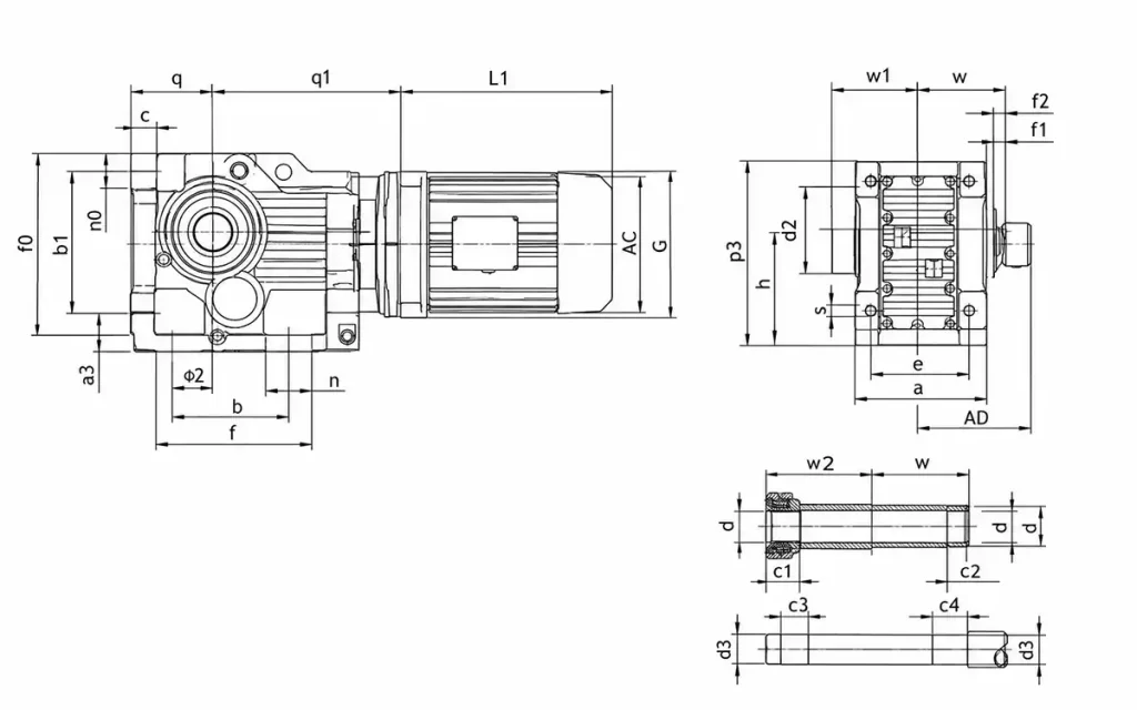
Motor frame combinations vary by model. Overall length, shaft dimensions, flange dimensions, and other installation dimensions should be matched to the selected size.
2.5 Technical Drawing Information
The corresponding technical drawing gives the dimensional details needed for model evaluation, including motor dimensions, shaft dimensions, mounting dimensions, and overall size.
3. How KHB Integrates with Industrial Equipment
Once the model is selected, integration mainly concerns the motor connection, driven shaft, mounting position, and surrounding clearance.
3.1 Motor and Gear Reducer Arrangement
Motor selection should match the required power, frame size, and connection dimensions. Available motor combinations vary across the KHB models.
3.2 Hollow Shaft and Machine-Side Shaft Connection
The machine-side shaft enters the KHB hollow output shaft. Shaft diameter, insertion depth, position, and connection method should match the equipment design.
3.3 Installation Position and Drive Layout
The mounting position depends on the machine structure and drive direction. Keep the motor, gearbox, and driven shaft aligned with the intended transmission path.
3.4 Installation Space and Clearance
Allow sufficient room around the assembly for installation and connection work. Before finalizing the layout, confirm:
- Motor envelope
- Overall gearbox size
- Shaft position
- Mounting points
- Required clearance
The selected model drawing can then be used for the final dimensional check.
4. KHB Series Gear Reducer Applications
KHB fits industrial drive arrangements where a hollow output shaft connects the gearbox to the driven machine. Common application areas include conveying, material handling, production lines, and packaging equipment.
4.1 Conveyor Systems
Belt conveyors, chain conveyors, and pallet conveyors can use KHB for controlled-speed drive transmission. The hollow shaft accommodates the corresponding conveyor drive shaft.
4.2 Screw Conveyor Equipment
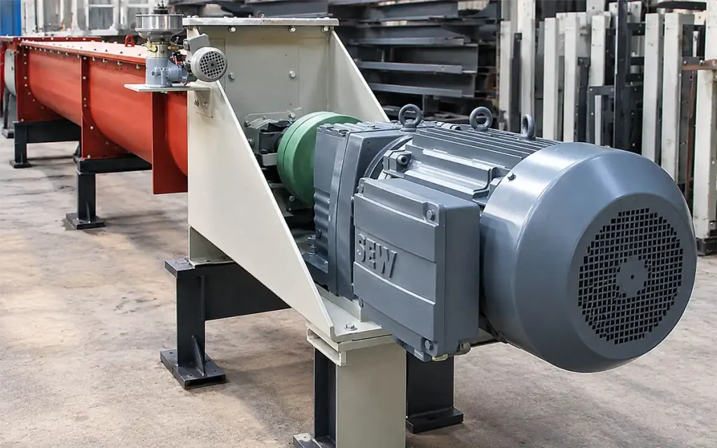
Screw conveyors are another suitable application. Reduced-speed rotation is transferred from the motor through KHB to the conveying mechanism.
4.3 Material Handling Equipment
Material transfer equipment, pallet handling equipment, and transfer conveyors can incorporate KHB where the machine-side shaft matches the hollow output connection.
4.4 Production Line Conveying Equipment
Production-line conveyors, feeding sections, and transfer sections can use KHB as part of their motor-driven transmission system.
4.5 Packaging and Transfer Equipment
Packaging conveyors and sorting or transfer equipment can also incorporate KHB when the shaft connection, operating speed, and installation arrangement suit the machine design.
5. How to Select the Right KHB Series Gear Reducer?
A practical selection path is:
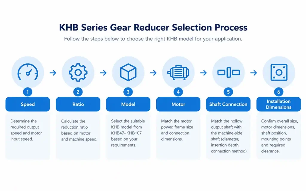
Speed → Ratio → Model → Motor → Shaft Connection → Installation Dimensions
Step 1. Determine the Required Output Speed
Start with the machine’s target operating speed and the motor input speed. These values establish the basic reduction requirement.
Step 2. Calculate the Reduction Ratio
The required ratio comes from the relationship between motor speed and machine output speed. Select a ratio that matches the intended operating point.
Step 3. Choose the KHB Model
Select from KHB47–KHB107 according to the required ratio, drive requirements, and available gear unit size.
Step 4. Match the Motor
Motor power, frame size, and connection dimensions should correspond to the selected KHB model and machine requirements.
Step 5. Match the Hollow Shaft
Match the KHB hollow output shaft with the machine-side shaft, including shaft diameter, position, insertion depth, and connection method.
Step 6. Confirm Installation Dimensions
For the final layout, confirm the overall size, motor dimensions, shaft position, mounting points, and available clearance for the selected model.
6. KHB Series Gear Reducer FAQ
Q1: What is a KHB Series Gear Reducer?
KHB is a K Series gear reducer with a hollow output shaft for connection to driven equipment.
Q2: What does KHB mean?
KHB refers to the K Series hollow-shaft configuration.
Q3: What models are available?
The range covers KHB47–KHB107:
KHB47, KHB57, KHB67, KHB77, KHB87, KHB97, KHB107.
Q4: Does KHB have a hollow output shaft?
Yes. The hollow shaft connects directly with the driven equipment shaft.
Q5: What equipment can use a KHB Gear Reducer?
Typical applications include conveyors, screw conveyors, material handling equipment, production-line conveying equipment, and packaging or transfer equipment.
Q6: Can KHB be used for conveyor systems?
Yes. Applications include belt conveyors, chain conveyors, and pallet conveyors.
Q7: What dimensions should be checked before installation?
Key dimensions include motor size, overall dimensions, shaft position, mounting points, and installation clearance.
7. Conclusion
If you are selecting a KHB Series Gear Reducer, share your required output speed, reduction ratio, motor power, machine-side shaft dimensions, and available installation space. Our team can help confirm the suitable KHB model and provide the corresponding technical drawing for installation reference.


