 +86 184 3796 0706
 info@destinytrans.com


Introduction
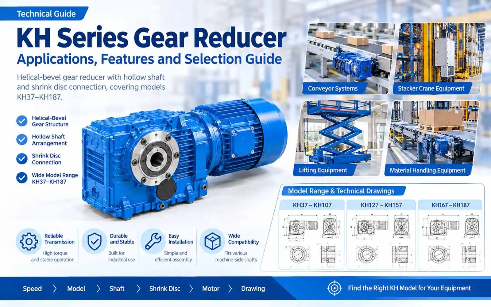
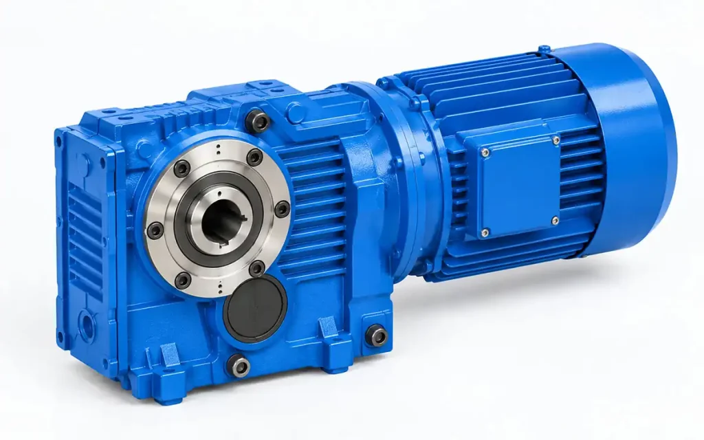
The KH Series Gear Reducer is a helical-bevel gear reducer with a hollow shaft and shrink disc for machine-side shaft connection. The series covers KH37–KH187, with model-specific installation and overall dimensions.
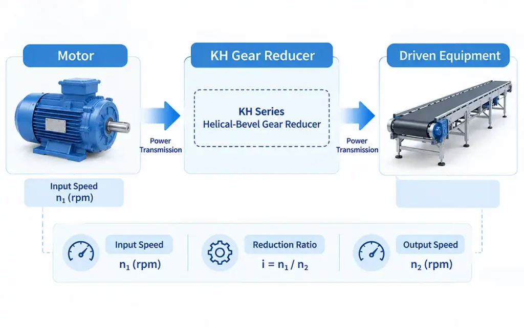
The basic transmission arrangement is:
Motor → KH Gear Reducer → Driven Equipment
This guide introduces the KH configuration, typical applications, equipment integration, and key points for model selection.
1. Why Do Industrial Machines Need a Gear Reducer?
Industrial motors often run at a higher speed than the driven equipment requires. A gear reducer adjusts the speed before power reaches the machine.
1.1 Drive Speed and Equipment Operation
The motor provides the input speed, while the machine requires a specific operating speed. The reducer lowers the motor speed to the required output speed for the equipment.
1.2 Basic Mechanical Power Transmission
The basic transmission path is:
Motor → Gear Reducer → Machine
The gear reducer forms the connection between the motor and the machine-side drive, transferring mechanical power to the driven equipment.
1.3 Basic Speed Data
Three basic values are useful when selecting a gear reducer:
- Input speed
- Required equipment speed
- Reduction ratio
2. KH Series Gear Reducer Features and Technical Characteristics
The KH Series is a helical-bevel gear reducer with a hollow shaft and shrink disc connection. The range covers KH37–KH187.
2.1 Helical-Bevel Gear Structure
The KH uses a helical-bevel gear arrangement to transmit power from the motor to the driven equipment. Its right-angle layout allows the input and output directions to be arranged at 90°.
Motor → KH Gear Reducer → Driven Equipment
2.2 Hollow Shaft Arrangement
The KH configuration uses a hollow output shaft for connection with the machine-side driven shaft. Shaft dimensions vary with the model size and need to match the equipment connection.
2.3 Shrink Disc Connection
The shrink disc secures the hollow shaft to the machine-side shaft. The shaft diameter and connection dimensions must match the selected KH model.
2.4 KH37–KH187 Model Range
The KH Series includes:
KH37, KH47, KH57, KH67, KH77, KH87, KH97, KH107, KH127, KH157, KH167, KH187
The basic external arrangement remains consistent across the range, while installation and overall dimensions vary by model size.
2.5 Mounting and Overall Dimensions
Model-specific dimensions include:
- Hollow shaft dimensions
- Mounting dimensions
- Flange dimensions where applicable
- Motor dimensions
- Overall dimensions
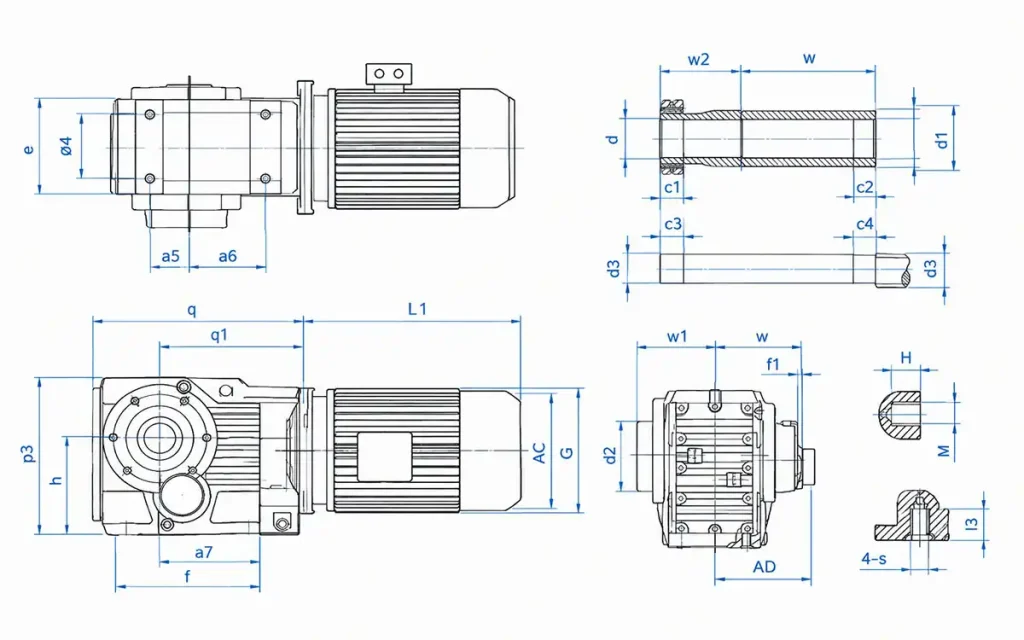
2.6 Technical Drawing Reference
The KH dimensional drawings cover three model groups:
- KH37–107 Mounting Dimensional Description
- KH127–157 Mounting Dimensional Description
- KH167–187 Mounting Dimensional Description
Use the relevant model drawing to check the shaft, mounting, motor, and overall dimensions before equipment integration.
3. How KH Gear Reducer Integrates with Industrial Equipment
The KH configuration can be integrated directly with the machine-side driven shaft. Its installation depends mainly on the shaft connection, drive direction, and available space.
3.1 Direct Machine-Side Shaft Connection
The hollow shaft connects the gear reducer to the machine-side driven shaft. Check the shaft diameter and connection dimensions against the selected KH model.
3.2 Shrink Disc and Shaft Connection
Check the shaft diameter and connection dimensions before installing the shrink disc. Ensure the machine-side shaft matches the hollow shaft and shrink disc specifications of the selected KH model.
3.3 Right-Angle Drive Layout
The right-angle layout can suit equipment where the motor and driven shaft require different installation directions. Check the motor position, shaft direction, and surrounding components when planning the drive layout.
3.4 Equipment Installation Space
Allow sufficient clearance around the reducer body, motor, hollow shaft, machine-side shaft, and surrounding components.
4. KH Gear Reducer Applications
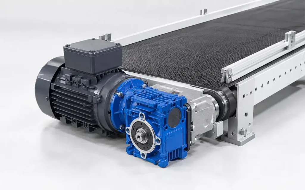
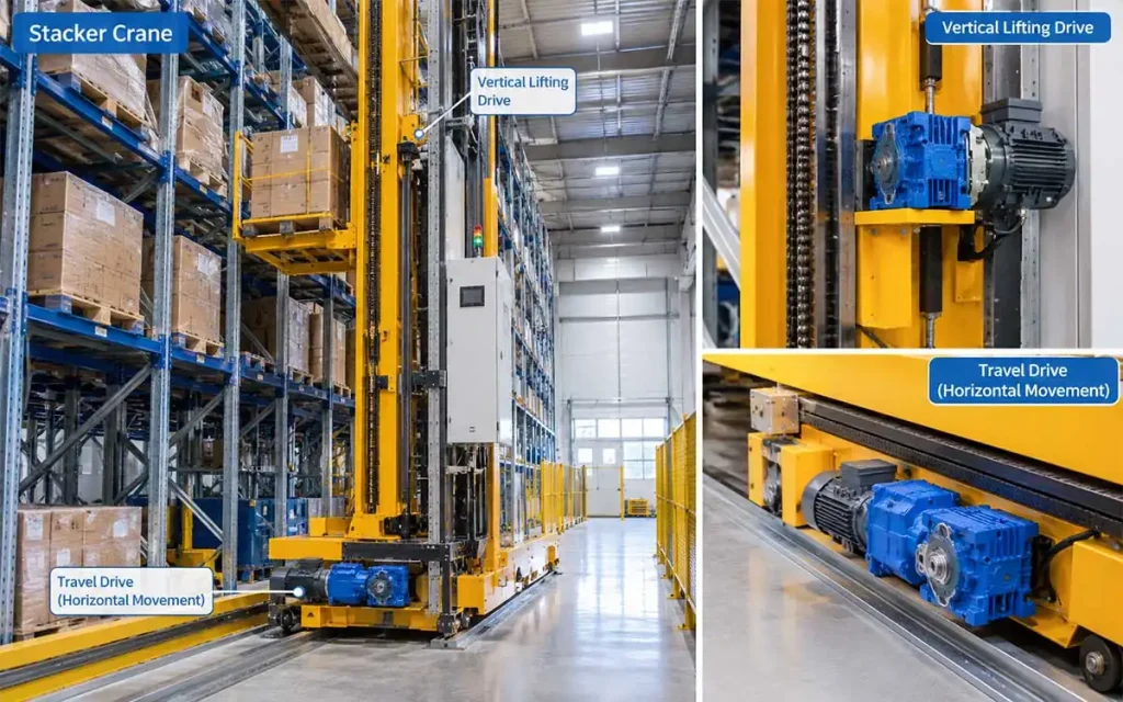
The KH Series can be used in several industrial drive applications where the motor and driven shaft need a defined transmission arrangement. The main application areas include conveyors, material handling, lifting equipment, and stacker cranes.
4.1 Conveyor Systems
KH gear reducers can be used in different conveyor configurations, including:
- Belt Conveyors
- Chain Conveyors
- Pallet Conveyors
- 2 Material Handling Equipment
The KH Series can be used for material movement and transfer applications, including:
- Material Transfer Systems
- Pallet Handling Equipment
4.3 Lifting Equipment
The KH Series can be used in lifting applications such as:
- Hoists
- Lifting Stations
- Scissor Lift Tables
4.4 Stacker Crane Equipment
The KH Series can also be used for:
- Stacker Crane Travel Drives
- Stacker Crane Lifting Drives
The suitable KH model depends on the required drive arrangement and machine-side connection.
5. How to Select the Right KH Gear Reducer?
A practical KH selection path is:
Speed → Model → Shaft → Shrink Disc → Motor → Drawing
Step 1: Determine Required Speed
Start with the motor/input speed, required equipment speed, and reduction ratio. These values establish the basic transmission requirement.
Step 2: Select the KH Model
Match the required reduction ratio and output speed with the appropriate model in the KH37–KH187 range.
Step 3: Machine-Side Shaft
Match the machine-side shaft diameter and connection with the hollow shaft dimensions of the selected KH model.
Step 4: Shrink Disc Connection
Match the shrink disc and shaft connection dimensions before installation.
Step 5: Drive Layout
Consider the motor position, driven shaft position, right-angle arrangement, and available installation space.
Step 6: Motor Configuration
Confirm the motor size, mounting dimensions, and overall motor length against the available space.
Step 7: Technical Drawing
Use the relevant KH dimensional drawing for the final dimensional check:
- KH37–107 Mounting Dimensional Description
- KH127–157 Mounting Dimensional Description
- KH167–187 Mounting Dimensional Description
Before ordering, match the shaft, mounting, motor, and overall dimensions with the machine layout.
6. KH Series Gear Reducer FAQ
Q1: What is a KH Series Gear Reducer?
The KH Series is a helical-bevel gear reducer with a hollow shaft and shrink disc connection.
Q2: What is the KH model range?
The KH Series covers KH37–KH187, with model-specific installation and overall dimensions.
Q3: What is a hollow shaft used for?
The hollow shaft connects the gear reducer to the machine-side driven shaft.
Q4: What is a shrink disc used for?
The shrink disc secures the hollow shaft to the machine-side shaft. The shaft diameters and connection dimensions must match.
Q5: What equipment can KH gear reducers be used for?
Typical applications include:
- Conveyor systems
- Material handling equipment
- Lifting equipment
- Stacker crane drives
Q6: Can KH gear reducers be used for conveyors?
Yes. Applications include belt conveyors, chain conveyors, and pallet conveyors.
Q7: Can KH gear reducers be used for lifting equipment?
Yes. The KH Series application range includes hoists, lifting stations, and scissor lift tables.
Q8: What information is needed to select a KH gear reducer?
Start with the required speed, machine-side shaft dimensions, shrink disc connection, motor configuration, and installation dimensions.
7. Conclusion
The KH Series Gear Reducer fits equipment layouts that require a helical-bevel drive with a hollow shaft and shrink disc connection.
Looking for the right KH model for your equipment? Send us the required speed, machine-side shaft dimensions, motor configuration, and installation drawing. Our team can help match the KH model to your machine layout.
References
- KH37–107 Mounting Dimensional Description
- KH127–157 Mounting Dimensional Description
- KH167–187 Mounting Dimensional Description
- K Series Gear Reducer Technical Documentation
- K Series Gearmotor Application References
Note: Final KH model selection should be confirmed against the machine-side shaft, motor configuration, installation dimensions, and specific equipment requirements.


