 +86 184 3796 0706
 info@destinytrans.com


Introduction: Why Is It Important to Understand a Gear Drawing Before Purchasing?
When purchasing gears, a gear drawing is an important reference for confirming product requirements. Purchasing personnel do not need to master every mechanical drawing symbol, but they should be able to identify the information that affects quotation, manufacturing, installation, and inspection.
A gear drawing may include the gear type, module or diametral pitch, number of teeth, pressure angle, helix angle, hand, dimensions, material, heat treatment, accuracy grade, tolerances, and technical requirements. These specifications are interconnected. For example, the bore and keyway affect installation, while material, heat treatment, accuracy, and tolerances affect performance and meshing.
Quick Answer: Key Gear Drawing Specifications to Check
When reading a gear drawing, buyers should check the gear type, basic gear parameters, major dimensions, material, heat treatment, accuracy, tolerances, and technical requirements. For a gear pair or replacement gear, the mating gear, shaft, and installation conditions should also be verified.
1. Identify the Gear Type on the Gear Drawing First
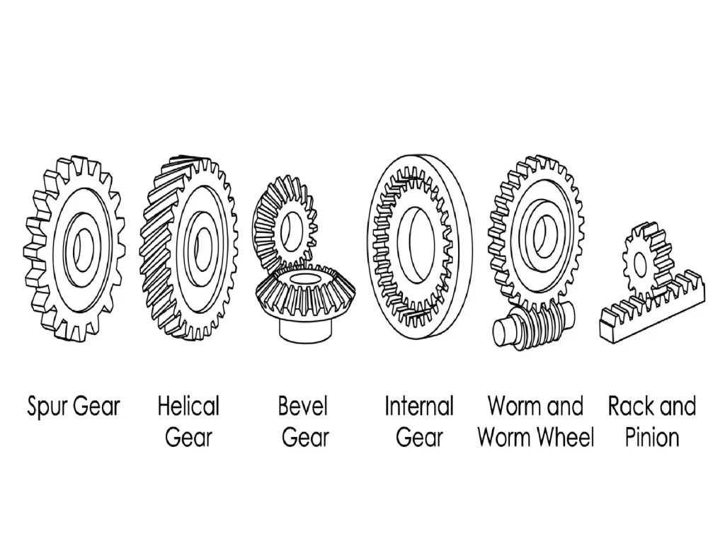
First determine whether the drawing shows a spur gear, helical gear, bevel gear, internal gear, worm and worm wheel set, or rack. Different gear types require different specifications.
For example, helical gears require helix angle and hand, while worm gearing should be checked as a matched set. Racks also require attention to tooth geometry, length, and mounting dimensions.
The basic rule is simple: identify the gear type first, then determine which parameters are critical for that type.
2. Check the Basic Gear Parameters on the Drawing
2.1 Module or Diametral Pitch
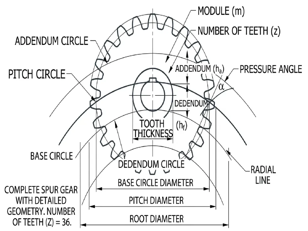
Module and diametral pitch (DP) describe tooth size. Module is mainly used in metric gear systems, while DP is common in inch-based systems.
Confirm the system and value shown on the drawing. For mating gears or replacement parts, check the corresponding parameters of the mating gear as well.
Module alone is not a complete gear specification. It must be considered together with tooth count, pitch diameter, pressure angle, and other relevant parameters.
2.2 Number of Teeth and Pressure Angle
The number of teeth affects the transmission relationship and is related to pitch diameter. For a gear pair, confirm the tooth counts of both gears. For multi-stage transmissions, the overall ratio should be checked across the complete system.
20° pressure angle is common, but it should not be assumed. The drawing should be the primary reference, especially for replacement gears or gears supplied as matched pairs.
If only an old gear or sample is available without a complete drawing, do not guess the pressure angle from appearance alone. Further measurement and verification may be necessary.
A replacement gear should not be ordered based only on outside diameter and tooth count. Module, pressure angle, tooth thickness, and mating gear parameters also need to be verified.
2.3 Helix Angle and Hand
For helical gears, confirm the helix angle and hand, normally specified as left-hand or right-hand. Both affect the mating relationship and must be checked against the mating gear.
2.4 Other Gear Pair and Tooth Parameters
Some gears may also specify a profile shift coefficient, tooth thickness, span measurement, or measurement over pins/balls (M value). These should be confirmed when included on the drawing rather than assumed from standard values.
For gear pairs, also check transmission ratio, backlash, and center distance, together with the mating gear specifications and installation conditions.
Do Not Consider Basic Parameters in Isolation
The key is to confirm that module, number of teeth, pressure angle, and, where applicable, helix angle and hand are compatible with the mating gear and design requirements.
3. Check the Main Gear Dimensions
After confirming the basic parameters, review the dimensions that affect the gear’s structure, installation, and surrounding clearance.
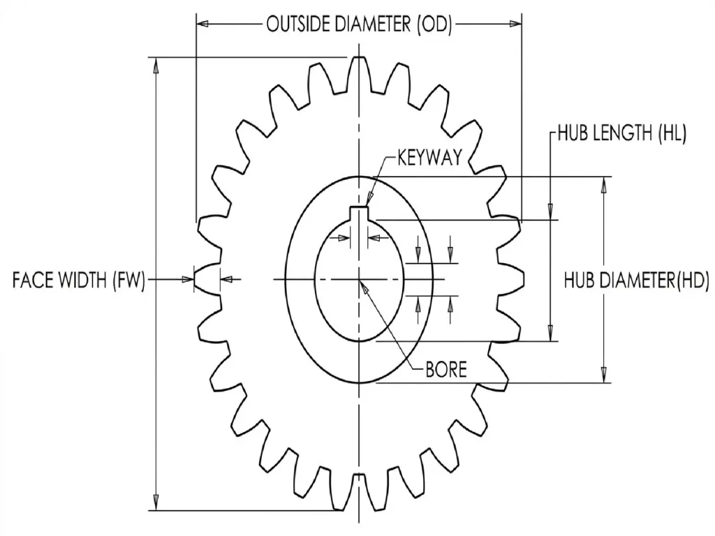
Key dimensions include:
- Outside diameter: affects radial installation space.
- Root diameter: helps define tooth-root geometry and potential interference.
- Pitch diameter: related to module and tooth count and important for meshing.
- Face width: affects load distribution, contact conditions, and axial space.
- Bore diameter: must be checked with its tolerance and fit requirements.
- Hub dimensions: include hub diameter, length, and axial positioning.
- Keyway dimensions: check width, depth, length, position, standards, and tolerances.
- Overall length: important for axial position and surrounding clearance.
For replacement parts, matching one dimension does not prove interchangeability. Outside diameter, bore, face width, hub, and keyway dimensions should be checked together with gear parameters, datums, and mating components.
4. Check Material and Heat Treatment Specifications
The drawing should clearly define the material grade, heat treatment, and hardness requirements.
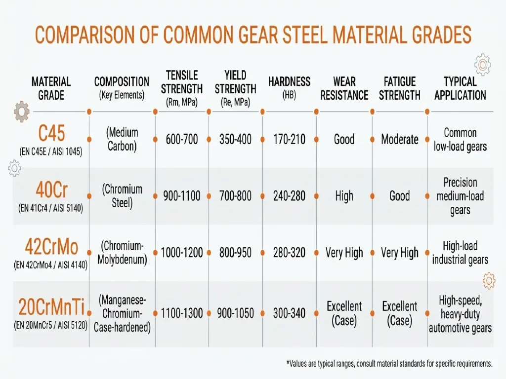
Common Chinese gear steel grades include C45, 40Cr, 42CrMo, and 20CrMnTi. International buyers may use EN or AISI/SAE grades as reference, but these should not be treated as automatic substitutes.
| Chinese Grade | International Reference Grade | Notes |
| C45 | EN C45E / AISI 1045 | Comparable medium-carbon steel grades; verify the applicable standard and delivery condition |
| 40Cr | EN 41Cr4 / AISI 5140 | Approximate reference grades; requirements may differ |
| 42CrMo | EN 42CrMo4 / AISI 4140 | Common approximate references; verify the material standard and heat treatment |
| 20CrMnTi | EN 20MnCr5 / AISI 5120 | Approximate reference only; 20CrMnTi contains Ti and has no exact international equivalent |
If the drawing specifies quenching and tempering, carburizing and quenching, induction hardening, or nitriding, also check surface hardness, core hardness, and effective hardened-layer depth where applicable.
Note: International grade references are for preliminary purchasing communication only. Similar grades may differ in chemical composition, mechanical properties, heat-treatment requirements, and applicable standards. The material standard stated on the drawing should remain the basis for quotation, manufacturing, and acceptance.
5. Check Accuracy, Tolerances, Datums, and Runout
General dimensional tolerances are not the same as gear accuracy requirements.
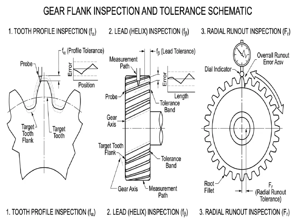
Dimensional tolerances control features such as outside diameter, bore diameter, and face width. Gear accuracy can also include profile, lead, pitch, and runout requirements.
The drawing may refer to ISO, DIN, AGMA, or GB/T standards. For cylindrical gears, flank accuracy may be specified according to ISO 1328-1:2013 or GB/T 10095.1-2022. Different standards do not necessarily use identical grading systems or evaluation methods, so the grade number alone should not be used to judge equivalence.
Also check:
- Profile tolerance
- Lead tolerance
- Pitch-related tolerances
- Radial or face runout
- Concentricity and other positional requirements
- Relevant datums
Datums define the references used to evaluate dimensions and geometric tolerances. For gears with shaft-and-key connections, bore, keyway, and end-face requirements may need to be controlled relative to specific datums.
Therefore, meeting dimensional tolerances does not automatically mean that the gear meets the required accuracy or installation requirements.
6. Review Technical Requirements and Notes
Important requirements may appear in the drawing notes rather than the main dimensional views.
Check for:
- Surface roughness
- Surface treatment
- Chamfers and deburring
- Rust prevention
- Part numbers or identification marks
- Other special machining or acceptance requirements
For example, the drawing may specify black oxide, phosphating, or a separate roughness requirement for a mounting surface. These details are part of the product specification and should be included in purchasing confirmation.
7. Confirm Whether the Drawing Is Ready for Quotation
A drawing generally provides a solid basis for quotation and technical confirmation when it clearly defines the gear type, basic parameters, dimensions, material, heat treatment, accuracy, and tolerances.
Before sending an inquiry, check for missing, unclear, or conflicting information. For a gear pair or replacement part, confirm that the mating gear, shaft, key, and installation conditions are also understood.
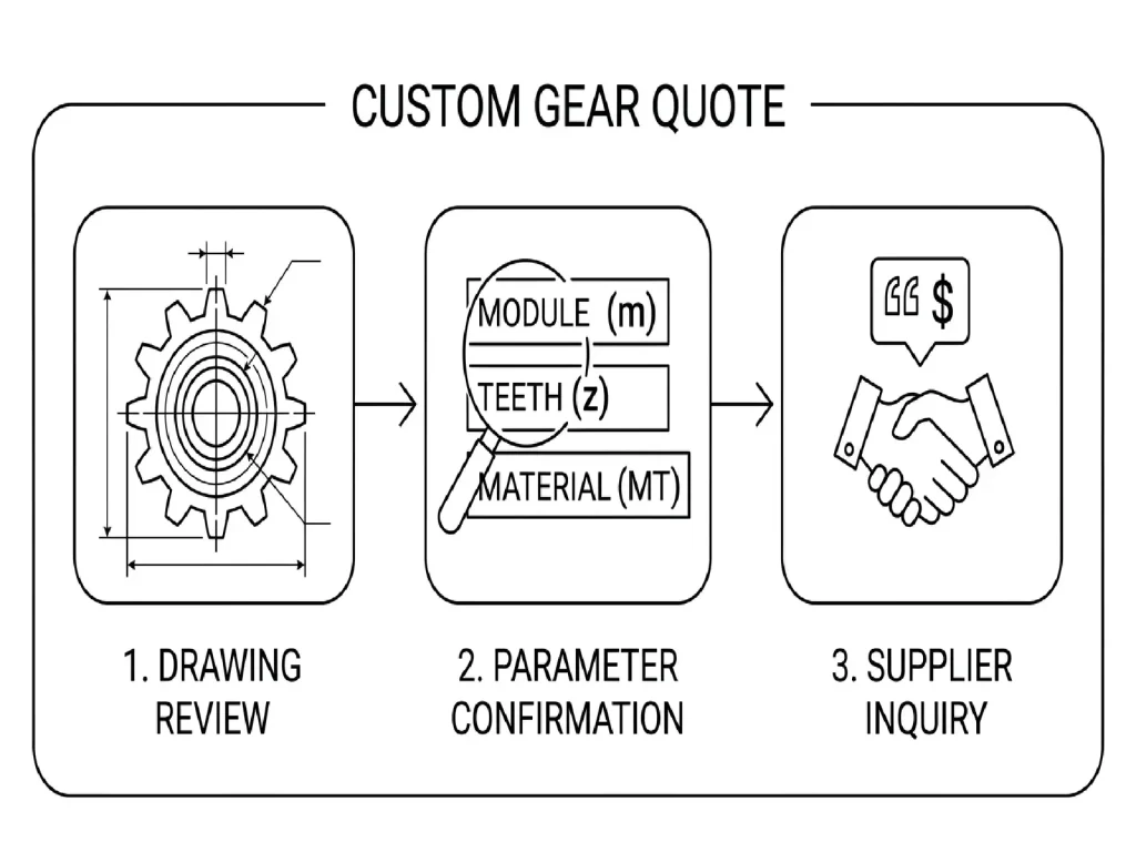
For custom gear quotations, information such as quantity, lead time, operating conditions, samples, and quality documentation may also be required. See our custom gear quotation guide for a complete checklist.
8. Gear Drawing Checklist Before Placing an Order
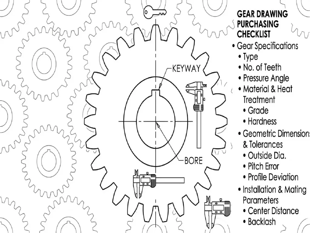
Before placing an order, use the following checklist to review the drawing item by item. The most common mistakes are failing to verify mating parameters, assuming 20° is the default pressure angle, and treating general dimensional tolerances as equivalent to gear accuracy requirements.
| Check Item | What Should Buyers Confirm? |
| Gear Type | Spur, helical, bevel, internal gear, worm and worm wheel set, or rack |
| Basic Parameters | Module or DP, number of teeth, pressure angle, and applicable helix angle and hand |
| Tooth Parameters | Profile shift, tooth thickness, span measurement, or M value where specified |
| Main Dimensions | Outside diameter, pitch diameter, root diameter, face width, bore, hub, and overall length |
| Installation | Bore tolerance, keyway, fit requirements, and relevant datums |
| Gear Pair | Transmission ratio, backlash, center distance, and mating gear specifications |
| Material & Heat Treatment | Material grade, treatment method, hardness, and hardened-layer requirements |
| Accuracy & Tolerances | Accuracy standard, grade, profile, lead, pitch, and runout requirements |
| Technical Requirements | Roughness, surface treatment, chamfers, deburring, and special notes |
| Drawing Completeness | No missing, unclear, or conflicting dimensions or notes |
| Supporting Information | Mating gear, shaft, key, and installation conditions for replacement parts |
If any critical item is unclear, confirm it with the supplier before placing the order rather than making assumptions.
9. What Should You Do If the Drawing Is Incomplete?
If a complete engineering drawing is unavailable, organize the available gear sample, photos, previous drawings, and basic dimensions. Information about the mating shaft, key, or gear should also be provided where possible.
Basic data such as tooth count, outside diameter, bore diameter, face width, and keyway dimensions can support preliminary identification and technical verification.
However, for high-precision, complex, or tightly matched gears, photos and basic dimensions are usually not enough to replace a complete engineering drawing. Additional measurement and inspection may still be required.
FAQ
1. What Are the Most Important Parameters on a Gear Drawing?
The most important parameters depend on the gear type, mating relationship, and operating conditions. In general, check module or DP, number of teeth, pressure angle, helix angle and hand where applicable, profile shift, tooth thickness, material, heat treatment, accuracy, bore, and key dimensions and tolerances.
2. What Is the Difference Between General Dimensional Tolerances and Gear Accuracy Grades?
Dimensional tolerances control features such as outside diameter, bore, and face width, while gear accuracy also covers profile, lead, pitch, and runout. A gear can meet dimensional tolerances without meeting the required gear accuracy grade.
3. How Can You Confirm the Hand of a Helical Gear From a Drawing?
Check whether the drawing specifies left-hand or right-hand, then verify it with the helix angle and mating gear. If the hand is not clearly defined, clarify it before production.
4. Why Can Two Gears With the Same Outside Diameter and Bore Diameter Still Be Non-Interchangeable?
Interchangeability also depends on module, number of teeth, pressure angle, tooth profile, accuracy, and the mating relationship. Matching outside and bore diameters alone is not sufficient.
5. How Should the Profile Shift Coefficient Be Interpreted?
The profile shift coefficient describes the displacement of the tooth profile relative to the standard rack position. If profile shifting is used, confirm that the coefficient matches the module, tooth count, and mating gear requirements.
It should not be assumed if it is not explicitly specified on the drawing.
6. How Is Gear Tooth Thickness Usually Inspected for Acceptance?
Depending on the drawing and inspection requirements, tooth thickness may be checked by tooth thickness measurement, span measurement, or measurement over pins/balls (M value).
For purchasing acceptance, confirm the required tooth thickness, allowable deviation, and measurement method.


