 +86 184 3796 0706
 info@destinytrans.com


Introduction
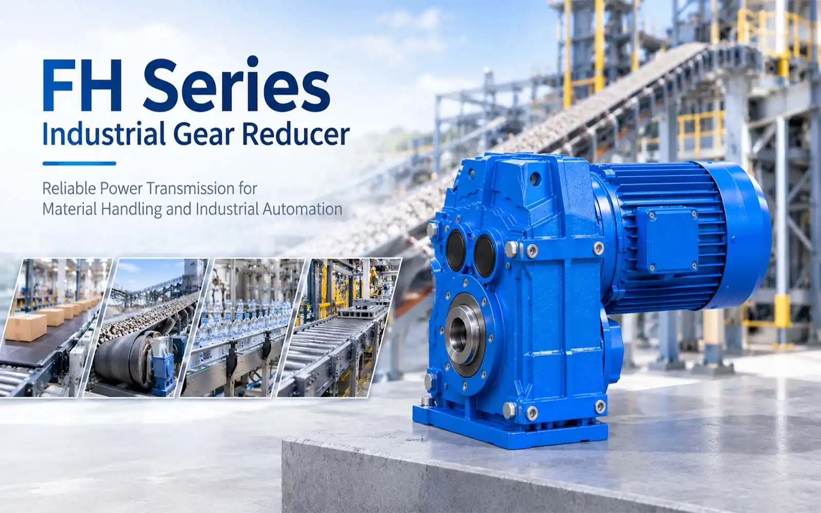
Industrial equipment often requires a gear reducer to lower drive speed and transmit power to the driven shaft. The FH Series Gear Reducer is designed for shaft-mounted drive applications.
Drive Source → FH Gear Reducer → Driven Shaft → Equipment
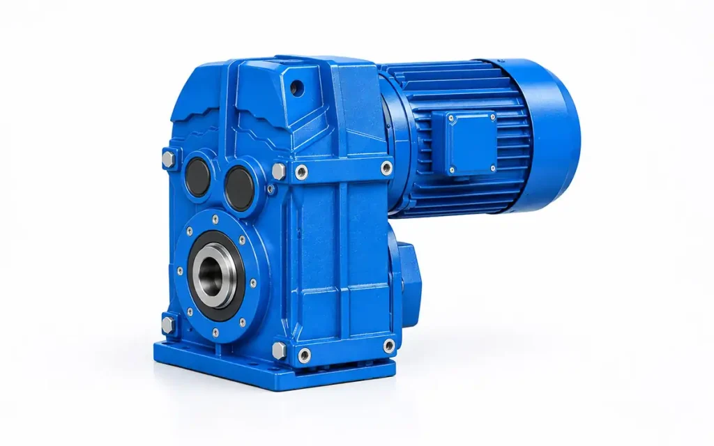
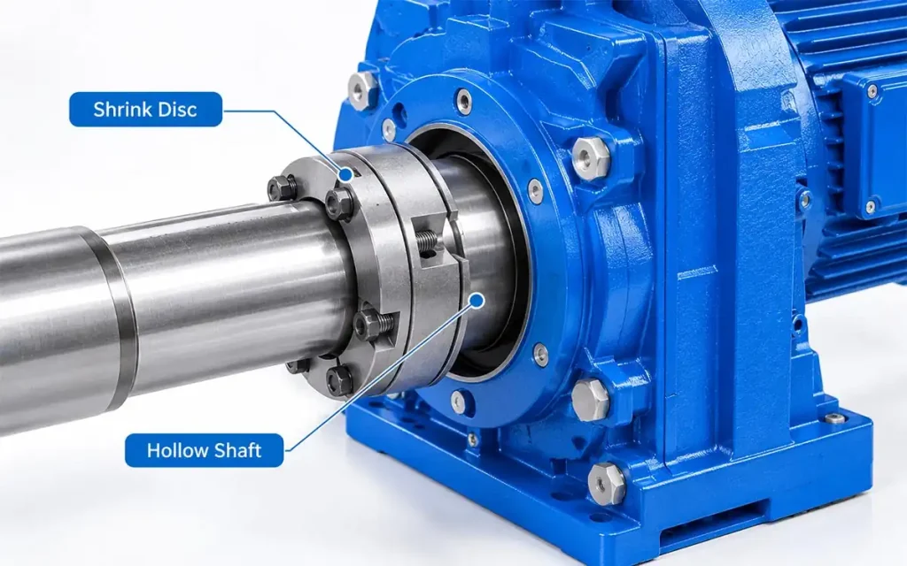
A key feature of the FH Series is its Hollow Shaft + Shrink Disc Mounting. The hollow shaft fits over the driven shaft, while the shrink disc secures the shaft connection.
The FH Series covers FH37–FH157. Model dimensions vary by size, making shaft dimensions, mounting space, and overall equipment layout important during model selection.
1. Why Do Industrial Machines Need a Gear Reducer?
Industrial machines often operate at a different speed from their drive source. A gear reducer lowers the input speed to suit the operating requirements of the equipment.
1.1 Drive Speed and Equipment Operation
The drive source may run faster than the connected machine requires. Speed reduction brings the drive speed closer to the required operating speed.
Drive Speed → Speed Reduction → Required Equipment Speed
1.2 Basic Mechanical Power Transmission
A gear reducer is part of the mechanical transmission between the drive source and the machine.
It receives power from the drive source and delivers it at a reduced speed.
1.3 Equipment Drive Requirements
The basic requirements are input speed, required operating speed, and reduction ratio.
Equipment connection and installation conditions are addressed during model selection.
2. FH Series Gear Reducer Features and Technical Characteristics
The FH Series uses a hollow shaft and shrink disc mounting arrangement for shaft-mounted equipment. Its main technical characteristics include the shaft connection, speed reduction, model dimensions, and installation requirements.
2.1 FH Hollow Shaft and Shrink Disc Structure
The hollow shaft provides the output connection between the gear reducer and the driven shaft.
The shrink disc secures the connection between the hollow shaft and the driven shaft.
2.2 Shrink Disc Connection
The shrink disc provides the clamping force needed to secure the shaft connection.
Its size and installation position should match the shaft dimensions and connection requirements of the selected FH model.
2.3 Shaft-Mounted Drive Arrangement
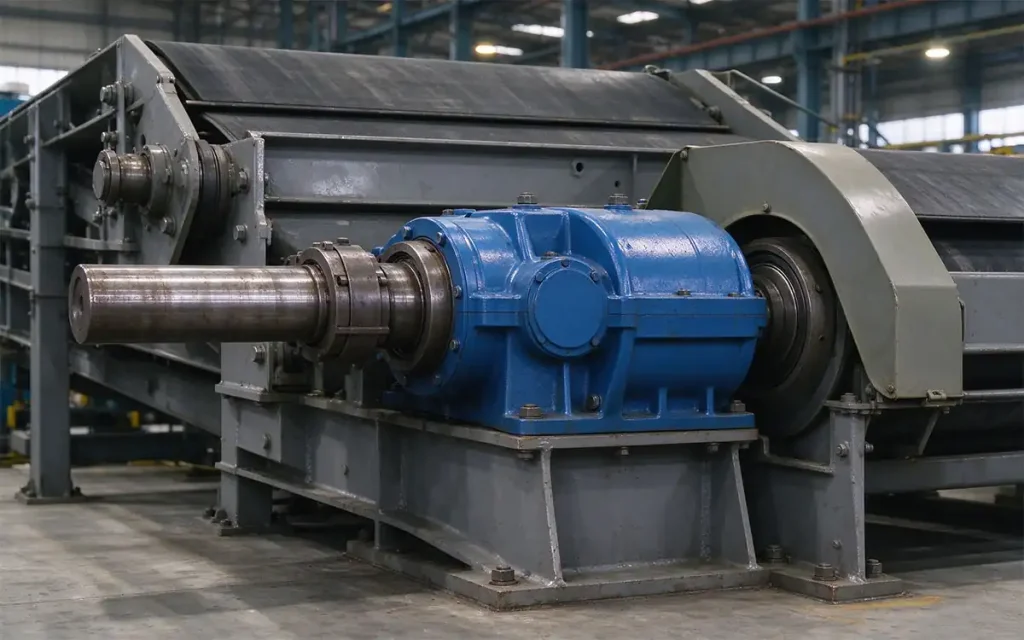
The shaft-mounted arrangement positions the gear reducer around the machine’s driven shaft.
The mounting arrangement should be checked together with the driven shaft design and available installation space.
2.4 Speed Reduction and Equipment Drive
The FH gear reducer forms part of the transmission path between the drive source and the driven equipment.
It reduces the input speed before power reaches the machine, allowing the output speed to suit the equipment’s operating requirements.
The required reduction ratio is determined by the relationship between the drive source speed and the target equipment speed.
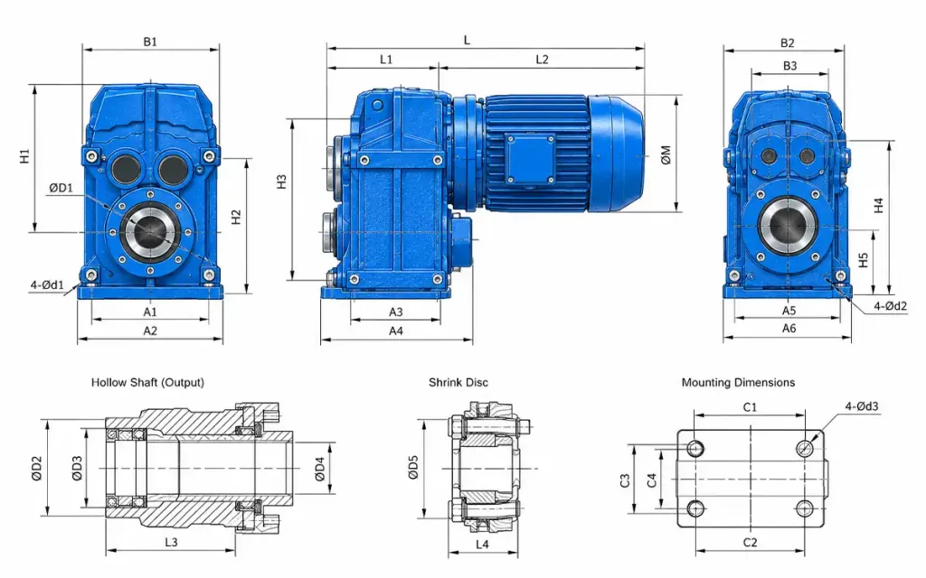
2.5 FH Model Sizes and Dimensions
The FH models are available in different housing sizes, with dimensions varying accordingly.
Important dimensions include:
- Overall dimensions
- Shaft dimensions
- Mounting dimensions
- Motor dimensions
These dimensions help determine whether the selected model fits the machine structure and available installation space.
2.6 Equipment Installation Layout
The gearbox position is influenced by the driven shaft location and the structure of the machine.
Available installation space also affects the gearbox position and connection arrangement.
2.7 Technical Drawing Review
The technical drawing shows the key dimensions needed to review the FH model before installation, including the shaft connection, mounting points, and overall envelope.
Reviewing the drawing helps confirm the dimensional relationship between the gearbox and the equipment before ordering.
3. Why Choose an FH Gear Reducer for Shaft-Mounted Applications?
The FH Series is suited to machine drive systems where the shaft connection, mounting arrangement, and available installation space are important parts of the equipment design.
Its configuration can support different machine layouts and driven shaft arrangements.
3.1 Supports Shaft-Mounted Equipment Integration
The FH Series supports equipment layouts where the gear reducer is integrated into an individual drive section.
This can help accommodate drive units integrated into individual machine sections.
3.2 Supports Shrink Disc Mounting
The shrink disc mounting arrangement fits machines designed around this type of shaft connection.
3.3 Fits Repeated Drive Cycles
The FH Series also fits machines with repeated drive cycles, such as:
- Conveying equipment
- Material transfer equipment
- Feeding equipment
- Production line equipment
Model selection is based on the machine’s operating speed and drive requirements.
3.4 Fits Different Equipment Drive Layouts
Machine designs may place the drive unit at different positions or use different driven shaft arrangements.
FH model selection should reflect these differences so the gear reducer fits the intended machine layout.
4. FH Gear Reducer Applications
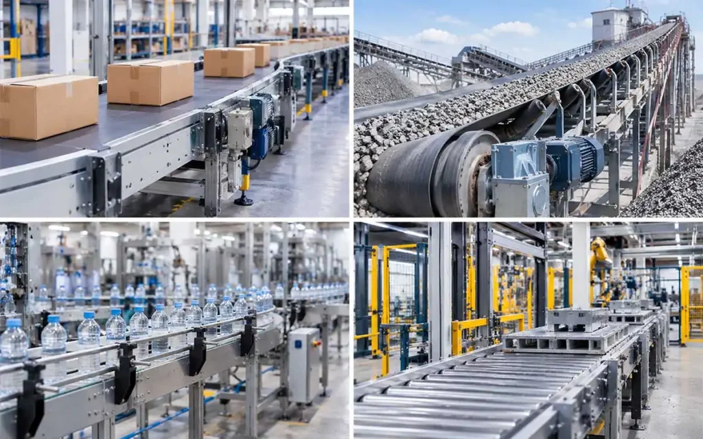
The FH Series suits machine drive systems used for conveying, material transfer, feeding, production, and processing.
4.1 FH Gear Reducers for Conveyor Systems
FH gear reducers suit belt conveyors, roller conveyors, and chain conveyors. They reduce drive speed and transmit power to the conveyor shaft as part of the conveyor drive system.
Drive Source → FH Gear Reducer → Hollow Shaft / Shrink Disc → Conveyor Shaft
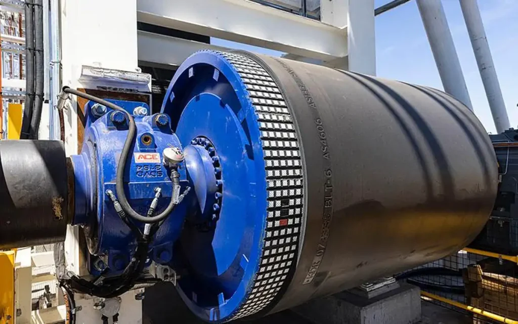
4.2 Material Handling and Transfer Equipment
The FH Series suits material transfer equipment, handling systems, and transfer mechanisms.
Typical considerations include material movement, shaft connection, transfer mechanism, and the available machine layout.
4.3 Feeding Equipment
FH gear reducers can serve as part of the drive system for automatic feeders, material feeding equipment, and feeding conveyor systems.
The required feeding speed, driven shaft dimensions, and equipment installation arrangement should be checked during selection.
4.4 Production Line Drive Sections
The FH Series suits production line equipment, assembly equipment, and material transfer sections that use individual drive units.
The gearbox position and connection arrangement should match the machine structure.
4.5 Processing and General Industrial Machinery
FH gear reducers also suit material processing machines, manufacturing equipment, and other shaft-driven machinery.
Selection is based on the required operating speed, driven shaft arrangement, and available space.
5. How to Select the Right FH Gear Reducer?
FH model selection starts with the machine’s operating speed and connection requirements, then moves to the installation layout and dimensions.
5.1 Speed Requirements
Start with the input speed and the required equipment speed to determine the suitable reduction ratio.
5.2 Shaft Connection
Check the driven shaft dimensions against the FH shaft connection, including the hollow shaft and shrink disc arrangement.
5.3 Mounting Arrangement
Confirm the gearbox position, mounting structure, and available space before selecting the model.
5.4 Equipment Layout and Dimensions
Compare the model dimensions with the machine layout to confirm that the gearbox fits the available space and connection position.
5.5 Technical Drawing Review
Use the technical drawing to verify the actual installation dimensions and shaft connection before ordering.
The final FH model should be selected according to the required speed, shaft connection, mounting arrangement, and equipment dimensions.
6. FAQ
Q1: What type of gearbox is the FH Series?
A hollow-shaft gear reducer with shrink disc mounting.
Q2: What is an FH hollow shaft gear reducer used for?
It is used in shaft-mounted equipment drive systems.
Q3: What is the purpose of the shrink disc?
It secures the hollow shaft to the driven shaft.
Q4: Can FH gear reducers be used for conveyors?
Yes. They suit belt, roller, and chain conveyors.
Q5: What equipment can use FH gear reducers?
Typical uses include conveyor, feeding, handling, production, and processing equipment.
Q6: What information is needed for FH model selection?
Input speed, required operating speed, shaft dimensions, mounting arrangement, and equipment dimensions.
Q7: Should the driven shaft dimensions be checked?
Yes. Check them against the gearbox shaft connection.
Q8: Can the technical drawing be reviewed before ordering?
Yes. It helps verify shaft and installation dimensions.
7. Conclusion
The FH Series Gear Reducer is designed for shaft-mounted drive systems using a hollow shaft and shrink disc mounting arrangement. Model selection should consider the required speed, shaft connection, mounting arrangement, and equipment dimensions.
Send us your equipment details or installation drawing for an FH gear reducer review.
Our technical team can help confirm the suitable FH model for your equipment or OEM project.
References
- FH Series Technical Drawing
- FH Series Gear Reducer Product Datasheet
- FH Series Gear Reducer Technical Catalog
- FH Hollow Shaft Dimension Drawings
- FH Shrink Disc Mounting Drawings
- Driven Shaft Connection References
- Conveyor and Material Handling Equipment Drive References
Note: Final model selection should be confirmed against the equipment shaft dimensions, installation structure, and application requirements.


