 +86 184 3796 0706
 info@destinytrans.com


Introduction
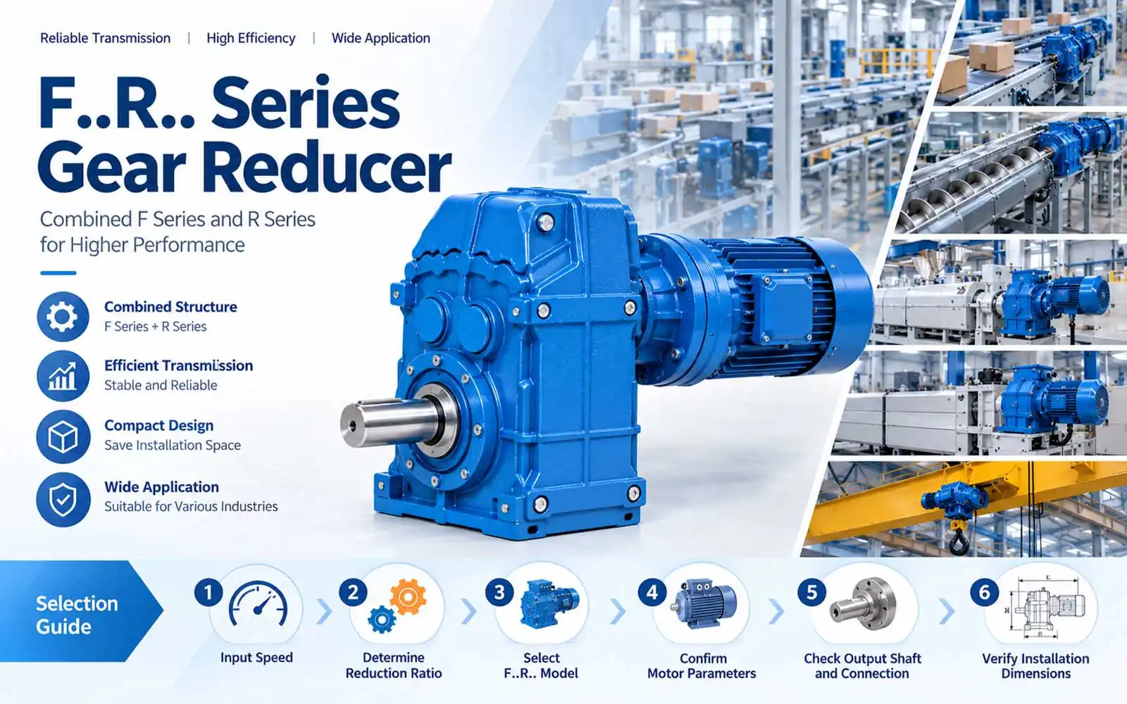
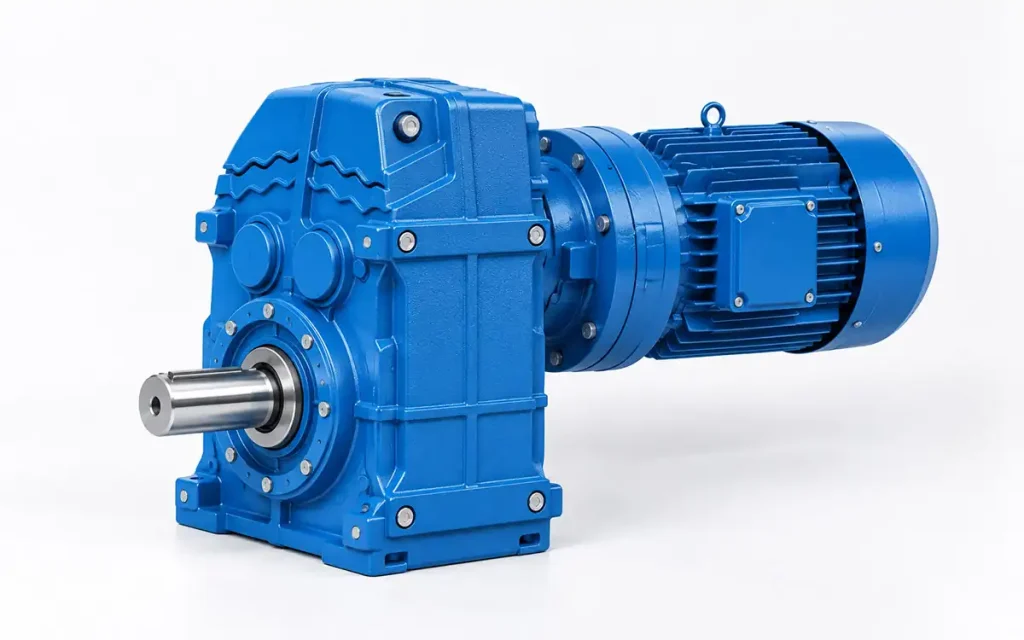
The F..R.. Series Gear Reducer is a combined gear unit that integrates F Series and R Series gearing into one drive arrangement. Models range from F..37R17 to F..157R97, with different gear unit sizes and motor combinations.
Motor → F..R.. Gear Reducer → Driven Equipment
This article covers the F..R.. structure, mounting dimensions, equipment applications, and key selection points.
1. Why Do Industrial Machines Need a Gear Reducer?
1.1 Motor Speed and Machine Speed
Industrial motors often run at a higher speed than the driven machine requires. A gear reducer matches the motor speed with the operating speed needed by the equipment.
1.2 Speed Reduction and Power Transmission
The gear reducer lowers the input speed and transfers mechanical power to the driven shaft. The selected ratio determines the resulting output speed.
1.3 Gear Reducer Drive Arrangement
The F..R.. unit forms the transmission section between the motor and driven equipment, providing the required speed reduction before power reaches the machine-side shaft.
2. F..R.. Series Gear Reducer Features and Technical Characteristics
The F..R.. Series combines F Series and R Series gear units in one drive assembly. The available models use different gear unit sizes and motor combinations.
2.1 Combined F and R Gear Unit Structure
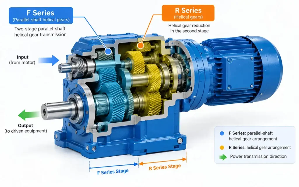
F..R.. is a combined type of F Series and R Series gear units. The two units work together as one multi-stage drive arrangement.
2.2 Parallel-Shaft and Helical Gear Arrangement
The F..R.. configuration combines the parallel-shaft helical gear arrangement of the F Series with the helical gear arrangement of the R Series.
2.3 Compact Combined Drive Arrangement
The combined arrangement can simplify the drive layout where installation space is limited. Model selection should take the machine layout and available space into account.
2.4 F..R.. Model Range
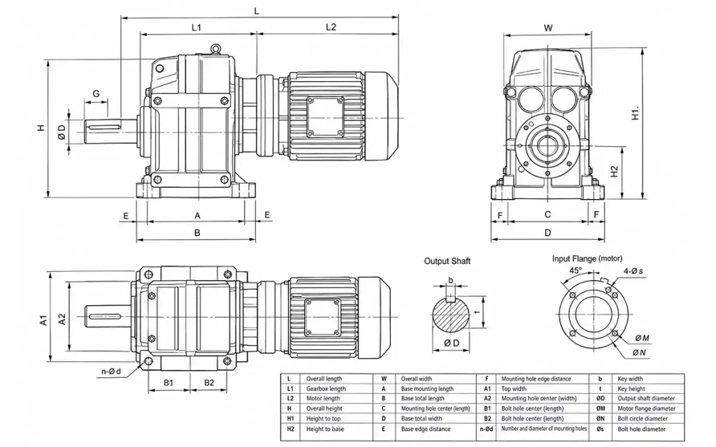
The main models shown in the technical drawing include:
- .37R17
- .47R17
- .57R37
- .67R37
- .77R37
- .87R57
- .97R57
- .107R77
- .127R77
- .127R87
- .157R97
The models mainly differ in gear unit size, motor frame combination, and related dimensions.
2.5 Mounting Dimensions and Technical Drawing
The technical drawing shows motor frame sizes, overall length, mounting dimensions, gear unit dimensions, and motor-related dimensions. Use the drawing for the selected F..R.. model when confirming installation dimensions.
3. How F..R.. Integrates with Industrial Equipment
F..R.. installation depends on the motor connection, machine-side shaft, mounting position, and available space.
3.1 Motor and Gear Reducer Arrangement
The motor is matched to the F..R.. gear unit according to the required motor frame size and installation dimensions. The technical drawing provides the relevant motor combinations for each model.
3.2 Gear Reducer Installation
The mounting position should suit the equipment layout and required drive direction. Allow enough space around the unit for installation and connection work.
3.3 Output Shaft and Machine-Side Connection
The output side connects to the driven machine or transmission component. Check the shaft position and connection dimensions against the machine-side requirements.
3.4 Installation Space and Dimensional Check
Before final selection, use the corresponding technical drawing to check:
- Overall dimensions
- Motor dimensions
- Shaft position
- Installation clearance
The selected model drawing should be used for final installation planning.
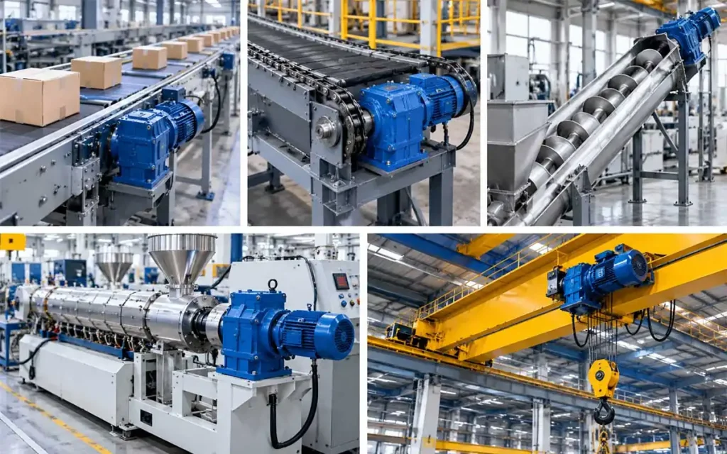
4. F..R.. Series Gear Reducer Applications
The F..R.. Series can be used in industrial drive systems where controlled speed reduction and a suitable mechanical connection are required.
4.1 Conveyor and Material Handling Equipment
F..R.. gear reducers can be used for conveyor systems and chain conveyors in material handling applications.
4.2 Screw Conveyor Equipment
The F..R.. configuration is also suitable for screw conveyors, where the drive unit transfers reduced-speed rotation to the conveying mechanism.
4.3 Process and Production Equipment
For process equipment and production machinery, F..R.. can serve as part of the motor-driven transmission system.
4.4 Press and Forming Equipment
Presses can use F..R.. gear reducers where the machine requires a defined reduced-speed drive arrangement.
4.5 Extrusion Equipment
F..R.. gear reducers can be incorporated into extruders as part of the equipment drive system.
4.6 Gantry Crane Drive Equipment
Gantry crane drives are another application area for F..R.. gear units, depending on the machine configuration and drive requirements.
5. How to Select the Right F..R.. Series Gear Reducer?
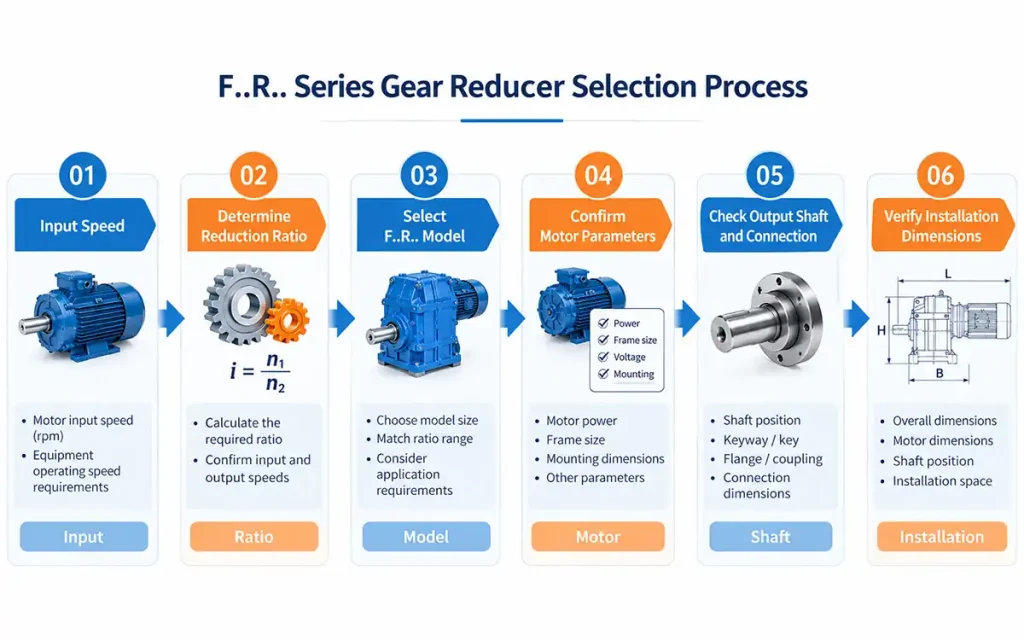
F..R.. selection starts with speed and ratio, followed by model, motor, shaft connection, and installation dimensions.
Speed → Ratio → Model → Motor → Shaft → Installation Dimensions
Step 1. Determine Required Speed
Confirm the motor input speed and the output speed required by the equipment.
Step 2. Determine Reduction Ratio
Calculate the required reduction ratio from the input and output speeds.
Step 3. Select the F..R.. Model
Choose the model based on the required ratio, equipment requirements, and available gear unit size.
Step 4. Confirm the Motor
Check the motor power, frame size, and related mounting dimensions against the selected model.
Step 5. Check Shaft and Equipment Connection
Confirm the output shaft position and connection dimensions match the driven equipment.
Step 6. Check Installation Dimensions
Use the corresponding F..R.. technical drawing to check:
- Overall dimensions
- Motor dimensions
- Shaft position
- Installation space
6. FAQ
Q1: What is an F..R.. Series Gear Reducer?
The F..R.. Series is a combined gear unit used for speed reduction and power transmission in industrial equipment.
Q2: What does F..R.. mean?
F..R.. identifies a combined configuration of F Series and R Series gear units within one drive assembly.
Q3: What is the structure of an F..R.. gear reducer?
It combines parallel-shaft helical and helical gear arrangements in one drive unit.
Q4: What F..R.. models are shown in the technical drawing?
The drawing shows models from F..37R17 to F..157R97, including 11 listed combinations.
Q5: What equipment can use an F..R.. gear reducer?
It is used in conveyor, screw conveyor, process, press, extrusion, and gantry crane drive applications.
Q6: Can F..R.. be used for conveyor systems?
Yes. It can be used in conveyor and chain conveyor drive systems.
Q7: Can F..R.. be used for screw conveyors?
Yes. Screw conveyors are one of the listed application areas.
Q8: What dimensions should be checked before selecting an F..R.. model?
Check the motor dimensions, reducer dimensions, shaft position, overall length, and installation space.
7. Conclusion
If you are selecting an F..R.. gear reducer, share your input speed, required output speed, reduction ratio, motor power, equipment connection dimensions, and available installation space.


