 +86 184 3796 0706
 info@destinytrans.com


Introduction: What Are External and Internal Gears?
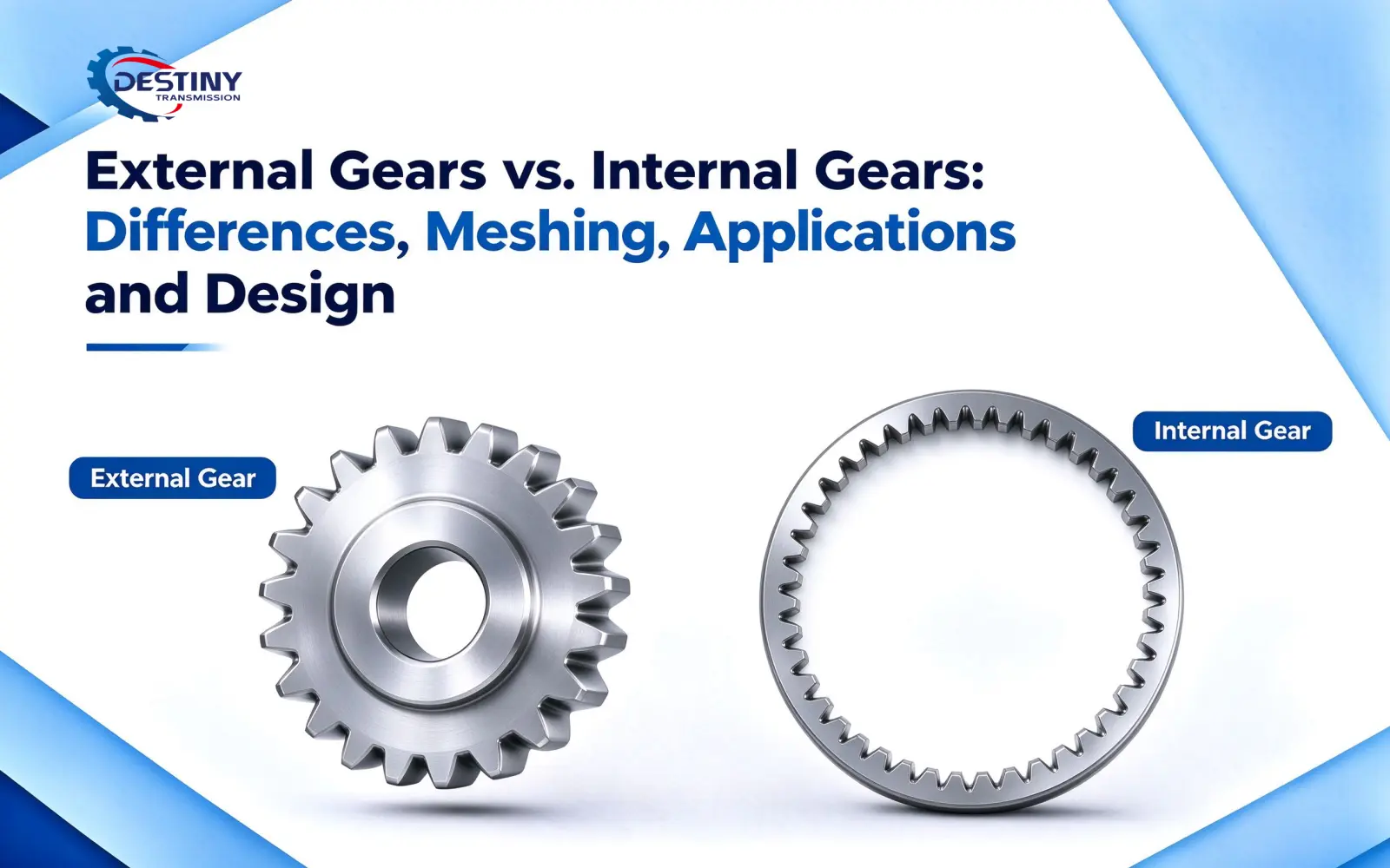
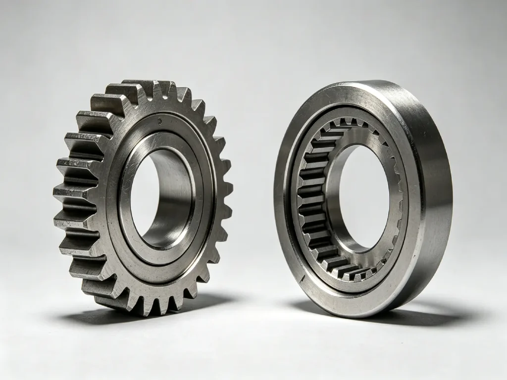
External gears and internal gears are both common gear types used in mechanical transmission systems. The most obvious difference is the location of the teeth: external gears have teeth formed around the outer circumference, while internal gears have teeth machined on the inside of a ring gear.
Although the difference may appear to be simply the position of the teeth, it affects the meshing method, direction of rotation, gear geometry, manufacturing process, and transmission layout. When designing a gear system, shaft arrangement, tooth number relationship, space constraints, load, and accuracy requirements should therefore be considered together rather than relying on module and tooth count alone.
Quick Answer: What Is the Difference Between External and Internal Gears?
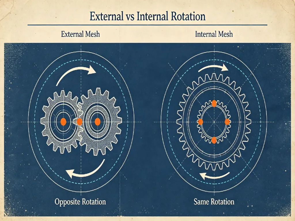
An external gear has teeth on its outer circumference. The most common arrangement is a pair of external gears meshing with each other. In external meshing, the driving and driven gears rotate in opposite directions.
An internal gear has teeth on the inner circumference of a ring gear and typically meshes with an external gear. Because this is internal meshing, the internal ring gear and external gear normally rotate in the same direction.
In addition to rotation direction, external and internal gears differ in structural form, tooth number relationships, manufacturing difficulty, and typical applications. Internal gears are especially common in planetary gear mechanisms because they can form a relatively compact transmission arrangement together with planet gears.
1. External Gear: What Is an External Gear?
An external gear is a gear with teeth distributed around its outer circumference. Common spur gears and helical gears can both use this configuration.
In a typical gear pair, one external gear meshes directly with another external gear. As the driving gear rotates, tooth surface contact drives the mating gear, causing the two gears to rotate in opposite directions.
External gears can be found in gear reducers, transmissions, machine tools, and general mechanical equipment.
In practical design, parameters such as module, number of teeth, pressure angle, pitch diameter, and face width are commonly considered. For helical gears, the helix angle also needs to be defined. These parameters must match the mating gear and the overall transmission system.
2. Internal Gear: What Is an Internal Gear?
Unlike external gears, the teeth of an internal gear are machined on the inner circumference of the gear ring. Its overall shape is usually ring-shaped, and it is also commonly referred to as an internal ring gear.
Internal gears are typically used together with external gears. Since the external gear is positioned inside the ring gear, the two form an internal mesh and normally rotate in the same direction.
This configuration can be advantageous in systems requiring same-direction rotation, coaxial arrangement, or a compact transmission layout.
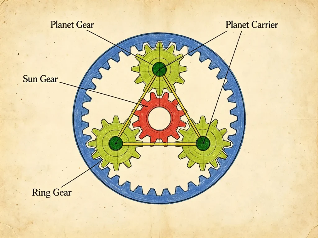
A planetary gear system is the most typical example. The internal ring gear meshes with the planet gears and works together with the sun gear to form a compact planetary transmission.
3. External Gear vs. Internal Gear: Key Differences
| Comparison Item | External Gear | Internal Gear |
| Tooth Location | Outer circumference | Inner circumference |
| Common Pairing | External gear with external gear | Internal gear with external gear |
| Meshing Type | External meshing | Internal meshing |
| Direction of Rotation | Normally opposite | Normally the same |
| Common Structure | Individual gears, gear pairs | Ring gears, planetary mechanisms |
| Space Characteristics | More open configurations | Suitable for compact, coaxial arrangements |
| Manufacturing Characteristics | Established machining processes and relatively accessible tooling | More restricted tool access and machining space |
| Typical Applications | Gear reducers, transmissions, mechanical drives | Planetary gears and other compact transmission systems |
In practical use, these are not simply the same type of gear with the teeth facing in different directions. Changing the position of the teeth also changes the meshing relationship and the way the overall transmission mechanism is designed.
4. Why Do External and Internal Gears Rotate in Different Directions?
The difference comes from their meshing geometry. A pair of external gears normally rotates in opposite directions, while an external gear meshing with an internal gear normally rotates in the same direction.
This kinematic difference affects the layout of the transmission and should be considered together with the input/output shaft arrangement when selecting a gear configuration.
5. Dimensional Relationships and Design Considerations for External and Internal Gears
Although both external and internal gears use basic parameters such as module, number of teeth, and pressure angle, the different tooth locations create different geometric relationships and design constraints.
For an external gear, the addendum circle lies outside the pitch circle, while the dedendum circle lies inside the pitch circle. Because the teeth of an internal gear are formed on the inside of the gear ring, the radial relationship between the addendum and dedendum circles is reversed relative to an external gear.
Center Distance and Tooth Number Relationship
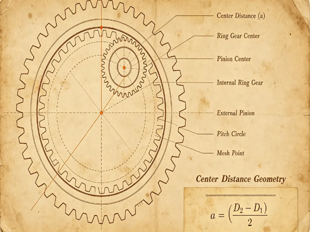
Under basic conditions with standard tooth profiles, the same module, and no profile shift, the theoretical center distance between two external gears can be expressed as:
a = m(z₁ + z₂) / 2
where a is the center distance, m is the module, and z₁ and z₂ are the tooth counts of the two external gears.
For an internal gear meshing with an external gear, the theoretical center distance depends on the difference between their tooth counts:
a = m(zᵣ − zₚ) / 2
where zᵣ is the tooth count of the internal ring gear and zₚ is the tooth count of the external gear.
These equations describe the basic theoretical geometry; actual working dimensions can differ when profile shift, backlash, or other design modifications are introduced.
For the same module and otherwise similar conditions, a smaller tooth count difference between the internal ring gear and external gear results in a smaller theoretical center distance. However, the difference cannot be reduced indefinitely because an excessively small difference may increase the risk of interference, including trochoid interference and trimming interference.
Profile Shift, Interference, and Undercut
In practical gear design, profile shift can be used to adjust the working geometry of a gear. In some designs, an appropriate profile shift coefficient can improve tooth geometry for gears with a small number of teeth and adjust the center distance or working pressure angle. However, profile shift is not a universal method for eliminating all interference problems. Its effect still needs to be evaluated based on tooth count, pressure angle, tooth profile, and the mating gear relationship.
When an internal gear is paired with an external gear, it is necessary to check the tooth number relationship, pressure angle, tooth profile, center distance, and interference conditions. Common interference conditions include involute interference, trochoid interference, and trimming interference. External gears with a low tooth count may also be subject to undercutting, while an excessively small tooth count difference between an internal gear and its mating external gear can increase the risk of trochoid or trimming interference.
Contact Ratio, Load, and Efficiency
The contact ratio, load-carrying capacity, and transmission efficiency depend on multiple design and operating factors rather than on gear type alone. Contact ratio is affected by factors such as tooth count, pressure angle, addendum, and helix angle. Load-carrying capacity is also related to material, face width, heat treatment, tooth profile accuracy, and operating load. Efficiency depends on factors including meshing method, load, speed, lubrication, and manufacturing accuracy.
These performance factors should therefore be assessed together with the operating conditions and mating gear parameters rather than assuming that one gear type inherently provides higher load capacity or efficiency.
Example: Simple Internal Gear Pair
Suppose a standard internal gear meshes with an external gear using module m = 2, with an internal ring gear tooth count of zᵣ = 60 and an external gear tooth count of zₚ = 40, without considering profile shift.
The theoretical center distance is:
a = 2 × (60 − 40) / 2 = 20 mm
If the external gear tooth count is increased to 50 while the module remains unchanged:
a = 2 × (60 − 50) / 2 = 10 mm
This example illustrates the geometric relationship only and does not by itself establish that the resulting gear pair is manufacturable or free from interference.
A smaller tooth count difference can reduce the theoretical center distance, but it does not necessarily make the design more appropriate. The applicable interference conditions, tooth geometry, and assembly requirements still need to be checked.
These relationships are especially important in a planetary gear system, where the sun gear, planet gears, and internal ring gear must satisfy the required tooth number and geometric conditions simultaneously.
6. Which Is Easier to Manufacture: External or Internal Gears?
From a manufacturing perspective, external gears generally have fewer machining constraints.
Because the teeth are located around the outer circumference, common processes such as hobbing, shaping, and gear grinding are well established, and machining and inspection are relatively straightforward. For conventional external gears, tooling, workholding, and inspection can generally be arranged more easily during production.
The main manufacturing challenge for internal gears comes from the available machining space and tool accessibility inside the gear. Because the teeth are located within the gear ring, tool entry and withdrawal are restricted by the ring’s internal diameter, face width, and structural dimensions. As a result, machining methods and tool selection are generally more constrained than for conventional external gears.
Depending on gear size, accuracy requirements, and production volume, different internal gear machining processes can be used. For high-precision internal gears, manufacturers also need to control profile accuracy, lead accuracy, pitch error, and the dimensional and positional accuracy of the gear ring.
For custom gear projects, the gear type should be evaluated together with the required tooth geometry, material, heat treatment, accuracy, and production quantity. Depending on the specification, the manufacturing process may include gear cutting, heat treatment, finishing, and final inspection. For internal gears, tooling accessibility and the selected machining method should be verified before production.
7. What Applications Are External and Internal Gears Used For?
Typical Applications of External Gears
Gear reducers and gearboxes frequently use external gears to transmit speed and torque between different stages.
In automotive transmission systems, various gear pairs also use external gear configurations to achieve different transmission ratios.
External gears are also widely used in machine tool drives and industrial machinery. Depending on the required transmission ratio, speed, torque, and shaft arrangement, configurations such as spur and helical gears can be used.
Typical Applications of Internal Gears
The most typical application of internal gears is the planetary gear system. In a planetary mechanism, the internal ring gear meshes with the planet gears and works together with the sun gear to form the planetary transmission. By changing which of the sun gear, planet carrier, and internal ring gear is fixed, used as the input member, or used as the output member, different transmission relationships can be achieved while maintaining a relatively compact structure.
Basic Planetary Gear Configurations
The Willis equation describes the speed relationship among the sun gear, ring gear, and planet carrier:
(nₛ − n𝚌) / (nᵣ − n𝚌) = −zᵣ / zₛ
where nₛ, nᵣ, and n𝚌 represent the rotational speeds of the sun gear, ring gear, and planet carrier, respectively, while zₛ and zᵣ represent the tooth counts of the sun gear and ring gear.
Three common basic configurations are shown below:
| Fixed Member | Input | Output | Speed Relationship | Basic Characteristic |
| Ring gear | Sun gear | Planet carrier | nₛ / n𝚌 = 1 + zᵣ / zₛ | Same-direction reduction; reduction ratio = 1 + zᵣ / zₛ |
| Sun gear | Ring gear | Planet carrier | nᵣ / n𝚌 = 1 + zₛ / zᵣ | Same-direction reduction; reduction ratio = 1 + zₛ / zᵣ |
| Planet carrier | Sun gear | Ring gear | nₛ / nᵣ = −zᵣ / zₛ | Sun gear and ring gear rotate in opposite directions; |nₛ / nᵣ| = zᵣ / zₛ |
These relationships show that the ring gear’s role in a planetary mechanism cannot be understood from its tooth location alone. Its motion depends on how the ring gear interacts with the sun gear and planet carrier, including which member is fixed, input, or output.
In addition to planetary gear systems, internal gears can also be used in certain rotary mechanisms, automatic transmission systems, and other coaxial or compact transmission configurations.
8. Can External and Internal Gears Be Directly Interchanged?
External and internal gears cannot simply be substituted with the same configuration.
Both gear types transmit motion and torque, but their tooth positions, meshing methods, and geometric relationships are different. Changing from an external gear to an internal gear therefore requires more than replacing one component. The complete transmission system should be reevaluated.
When changing the gear type, check the tooth count, module, pressure angle, center distance, tooth profile, and interference conditions. Also confirm that the internal and external gears meet the required meshing geometry and installation relationships.
The replacement gear must also meet the original transmission system’s requirements. These include installation space, rotation direction, and transmission ratio. Similar dimensions alone do not confirm interchangeability.
Therefore, when modifying equipment or replacing gears, evaluate the complete transmission mechanism. Do not compare the dimensions of individual gears alone. For custom gears, also confirm the manufacturing process, material, and accuracy requirements to ensure compatibility with the original transmission system.
9. How to Choose Between External and Internal Gears?
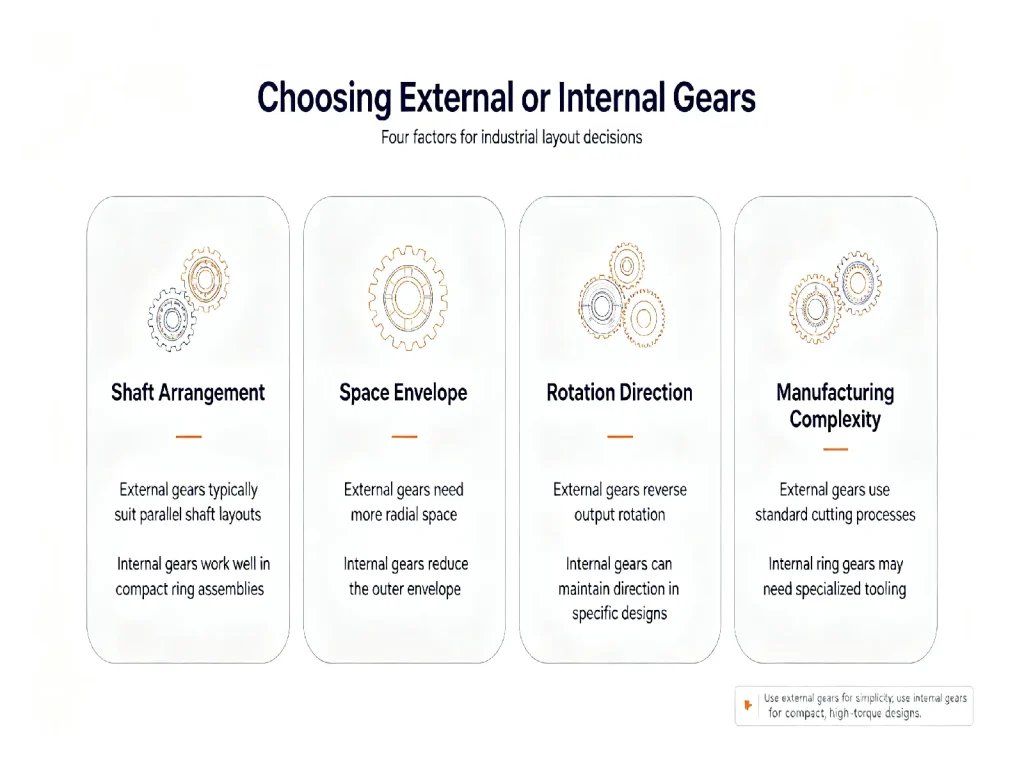
The choice between an external gear and an internal gear mainly depends on the transmission layout, meshing method, and manufacturing conditions.
When a system requires conventional power transmission between separate shafts, external gears are generally more straightforward and can make use of established machining processes.
Shaft Arrangement
Start with the relative position of the input and output shafts. For transmission mechanisms requiring a coaxial arrangement, internal gears can provide a layout that differs from a conventional external gear pair and are commonly used in compact planetary transmissions.
Rotation Direction
The required rotation direction should also be checked. If the transmission system requires the input and output to rotate in the same direction, first check whether an internal meshing arrangement meets the requirements of the mechanism. The specific shaft arrangement must also be considered.
Space Constraints
Available installation space is another key factor. When radial or axial installation space is limited, compare how different gear arrangements affect the overall dimensions. An internal gear allows an external gear to be positioned inside the ring, which can help create a more compact structure in certain transmission mechanisms.
Load and Speed
Operating conditions determine the required gear capacity. Torque, rotational speed, duty cycle, and impact loading directly affect the gear’s dimensions, material, heat treatment, and accuracy requirements. The choice between an external and internal gear therefore cannot be determined independently of the operating conditions.
Manufacturing Capability
Manufacturing capability becomes especially important for internal gears. Confirm in advance that the manufacturer has the necessary capabilities for internal gear machining, heat treatment, and precision inspection. This is especially important for high-precision or specially sized internal ring gears.
Accuracy Requirements
Accuracy should be specified according to the operating conditions. For equipment requiring high operating speed, low noise, or high transmission accuracy, the meshing condition, profile error, and lead error of the mating gears should also be checked rather than considering the accuracy grade of an individual gear alone.
FAQ
1. What Is an External Gear?
An external gear is a gear with teeth formed on its outer circumference. It commonly meshes with another external gear to transmit motion and torque.
2. What Is an Internal Gear?
An internal gear is a ring-shaped gear with teeth formed on its inner circumference. It commonly meshes with an external gear and is widely used in planetary gear systems.
3. Do Internal and External Gears Rotate in the Same Direction?
A pair of external gears normally rotates in opposite directions, while an external gear meshing with an internal gear normally rotates in the same direction. The difference comes from their meshing geometry.
4. Are Internal Gears More Difficult to Manufacture?
They can be more challenging to manufacture because the teeth are located inside the gear ring, which limits machining space and affects tool access, tool selection, and processing methods.
5. Are Internal Gears Used in Planetary Gearboxes?
Yes. An internal ring gear is an important component of many planetary gear systems and works with the sun gear and planet gears.
6. Can an External Gear Be Directly Replaced with an Internal Gear?
An external gear and an internal gear are not normally interchangeable without redesigning the mating relationship. Their different tooth positions and geometries affect gear dimensions, center distance, interference conditions, and the overall transmission layout.
Conclusion
The difference between an external gear and an internal gear begins with the position of the teeth, but it affects much more than their physical appearance.
External gears are widely used for conventional gear transmission, while internal gears are particularly common in planetary and compact coaxial mechanisms. The appropriate configuration depends on meshing geometry, shaft arrangement, space, load, speed, accuracy, and manufacturing conditions.
For custom gear projects, these factors should be evaluated together to ensure that the selected gear type is compatible with the complete transmission system. For custom external or internal gears, you can contact our team to discuss your gear requirements and technical specifications.


