1. What is an herringbone gear?
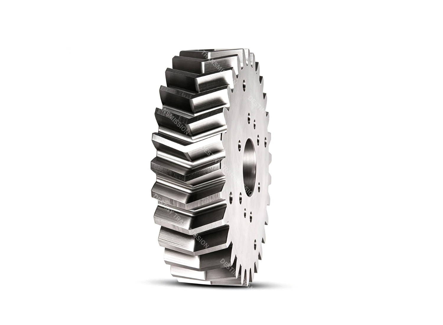
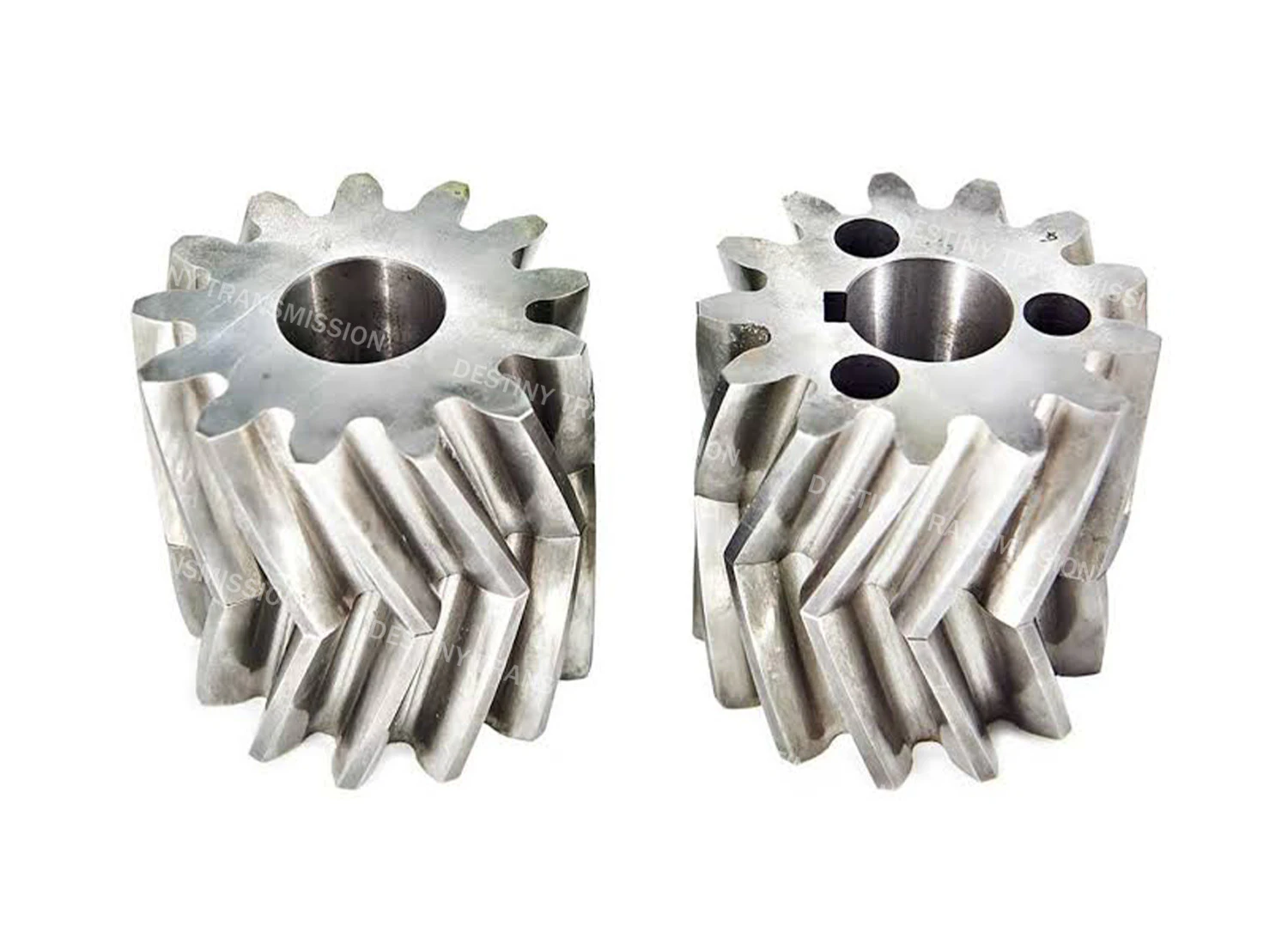
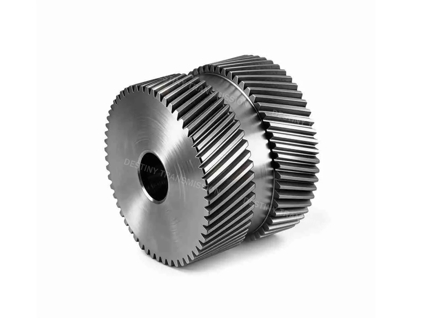
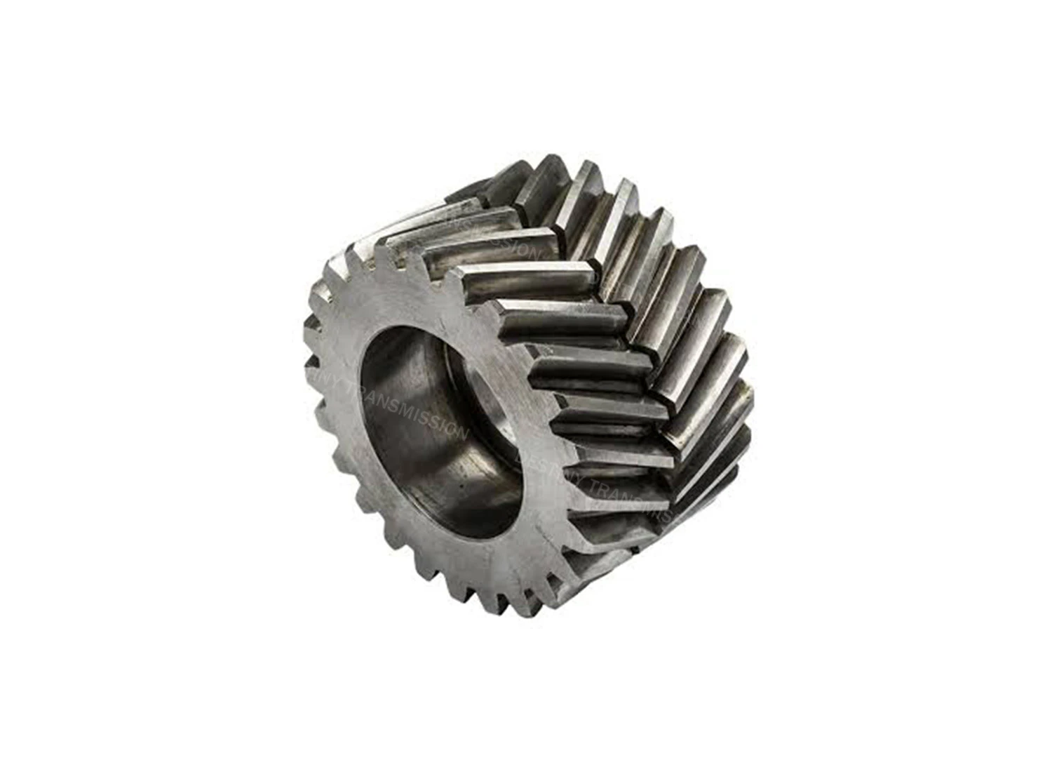
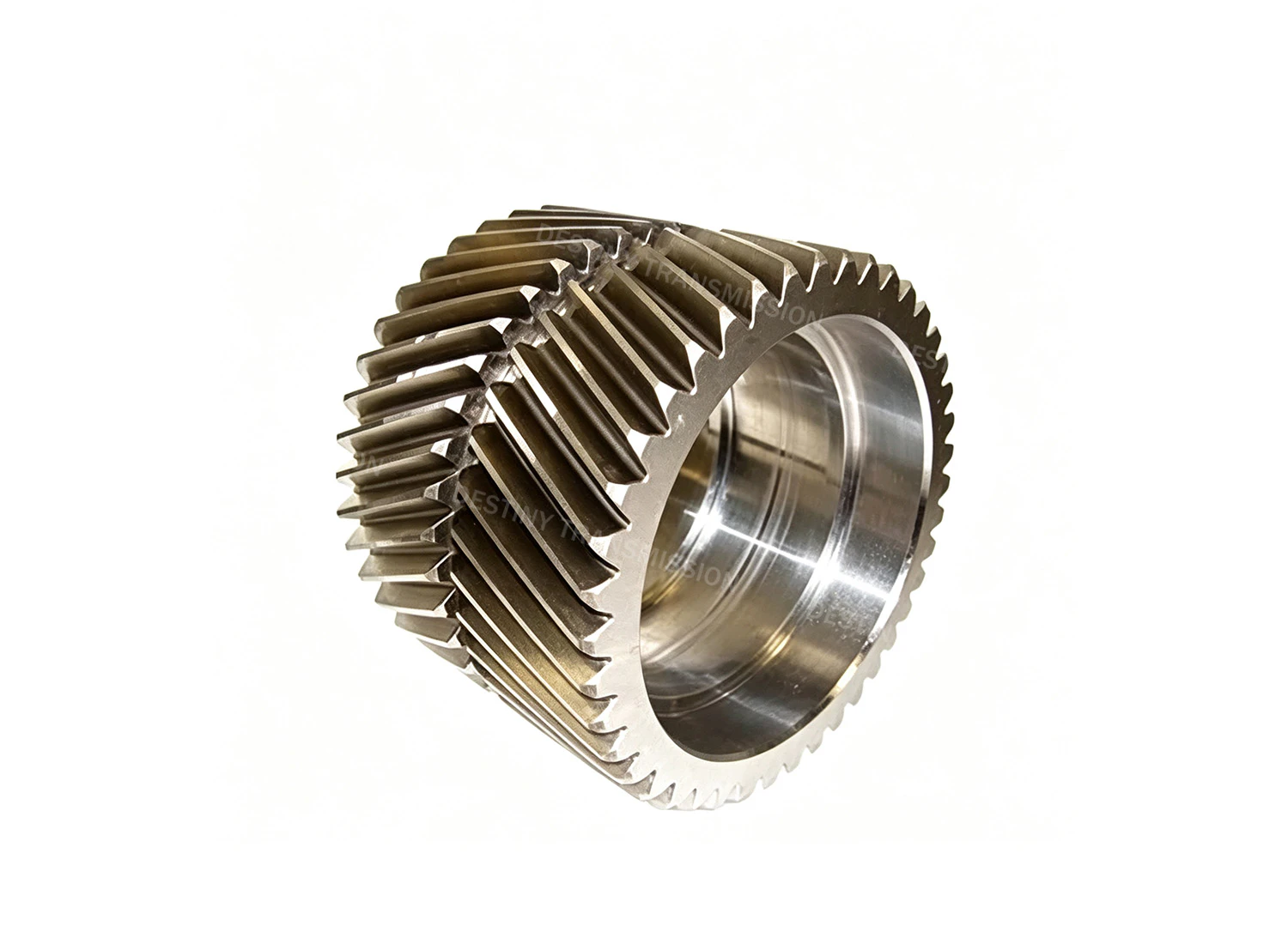
Also known as double helical gears in the industry, herringbone gears are a category of heavy-duty cylindrical gears built for parallel shaft transmission.
Put simply, a herringbone gear consists of two helical gear sections with equal helix angles and opposite rotational directions, joined symmetrically along the axis. The tooth profile forms a distinct herringbone pattern — the very feature that gives the gear its name.
They carry forward all the core strengths of helical gears: high contact ratio, smooth operation, and exceptional load-carrying capacity. At the same time, the axial thrust forces generated by the two opposing tooth halves cancel each other out completely. This removes the need for separate thrust bearings and allows for a simplified housing and shaft system design.
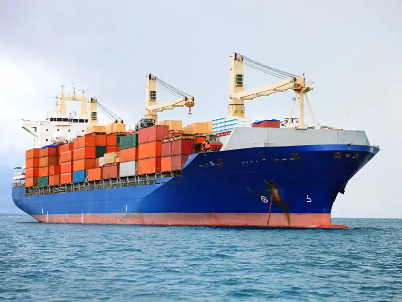
That said, herringbone gears demand higher machining accuracy and more complex production processes, which makes them significantly more expensive to manufacture than standard helical gears. For this reason, they are predominantly deployed in high-power, heavy-duty transmission scenarios including marine propulsion systems, steel rolling mills, wind turbine gearboxes and heavy mining machinery.
2.Core Structure and Transmission Characteristics
1.Tooth Profile and Structural Design
These gears use an industry-standard involute tooth profile with a nominal 20° pressure angle. Fundamentally, they are constructed from two helical gear segments with matching helix angles and opposite hand directions, symmetrically joined along the axis to create the characteristic herringbone tooth pattern. Two common construction types are available: one-piece and split-assembled. Large-module gears are typically machined with a tool withdrawal groove, while small-module, high-precision variants often use a one-piece groove-free design.
2.Meshing and Transmission Performance
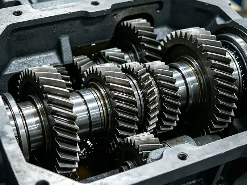
Herringbone gears inherit the smooth, gradual engagement and disengagement of helical gears, while boasting a higher contact ratio than standard single helical gears — meaning more teeth share the load at any given moment. This reduces operational shock, delivers smoother running and better noise reduction, and delivers a significant boost to load capacity, making them well suited for continuous heavy-duty operation over extended service hours.
3.Self-Balancing Axial Force
This is the defining advantage of herringbone gears. The axial thrust forces generated by the two opposing helical sections during meshing are equal in magnitude and opposite in direction, canceling each other out completely within the gear. The drive shaft and supporting bearings experience almost exclusively radial loads, eliminating the need for separate thrust bearings. There is also no need for axial reinforcement of the gear housing, which simplifies shaft system design and prolongs bearing service life.
4.Performance Limits and Manufacturing Constraints
Transmission efficiency is comparable to single helical gears of the same precision grade, at approximately 97% to 98%. The main drawback is the higher manufacturing barrier: stricter requirements for machine tools, cutting tools, and operator expertise drive production costs well above those of standard spur and helical gears. For this reason, they are almost exclusively used in heavy-duty, high-power applications; they offer very little cost advantage for light-load, small-module general transmission systems.
 +86 184 3796 0706
 info@destinytrans.com