1.What is a Helical Gear Shaft?
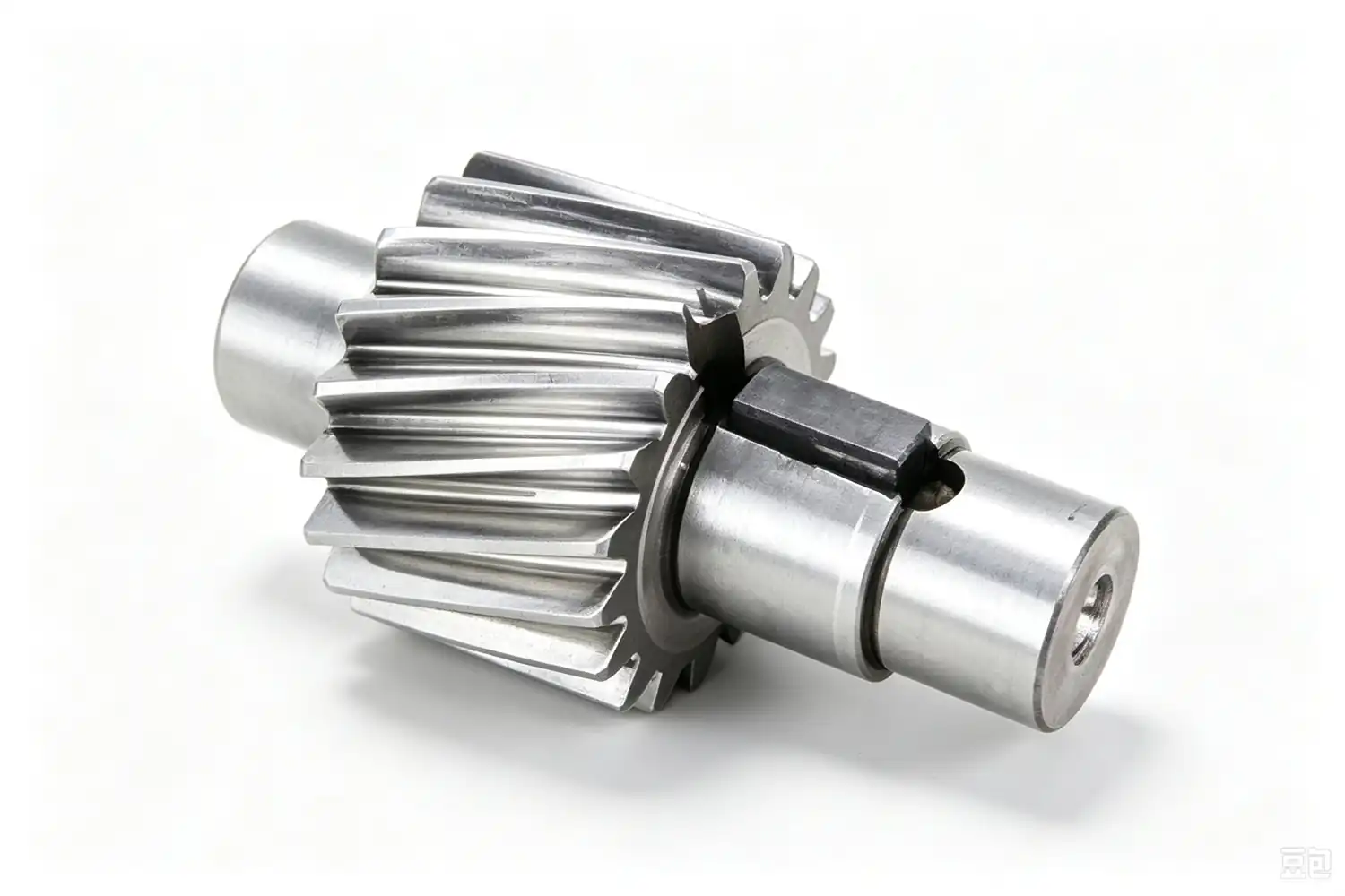
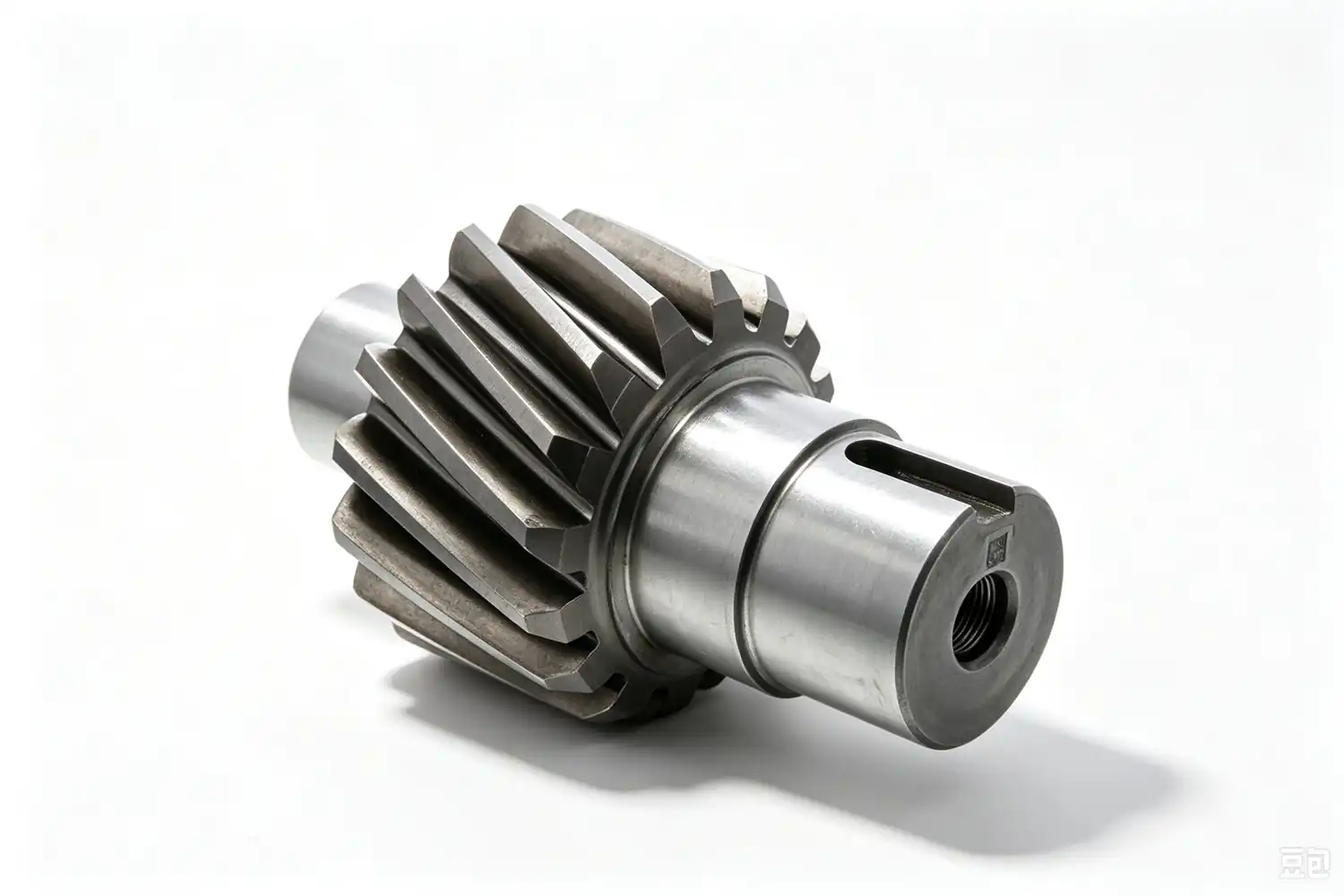
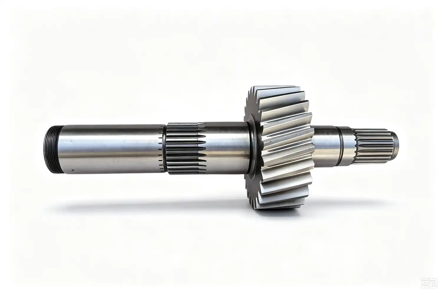
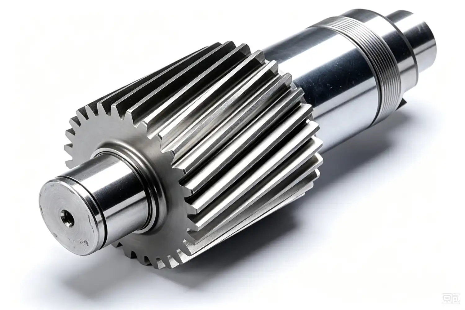
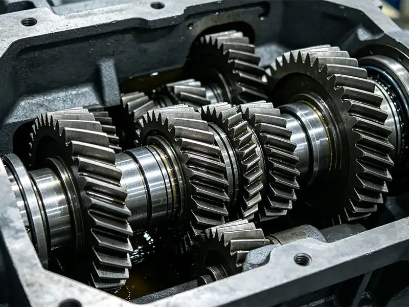
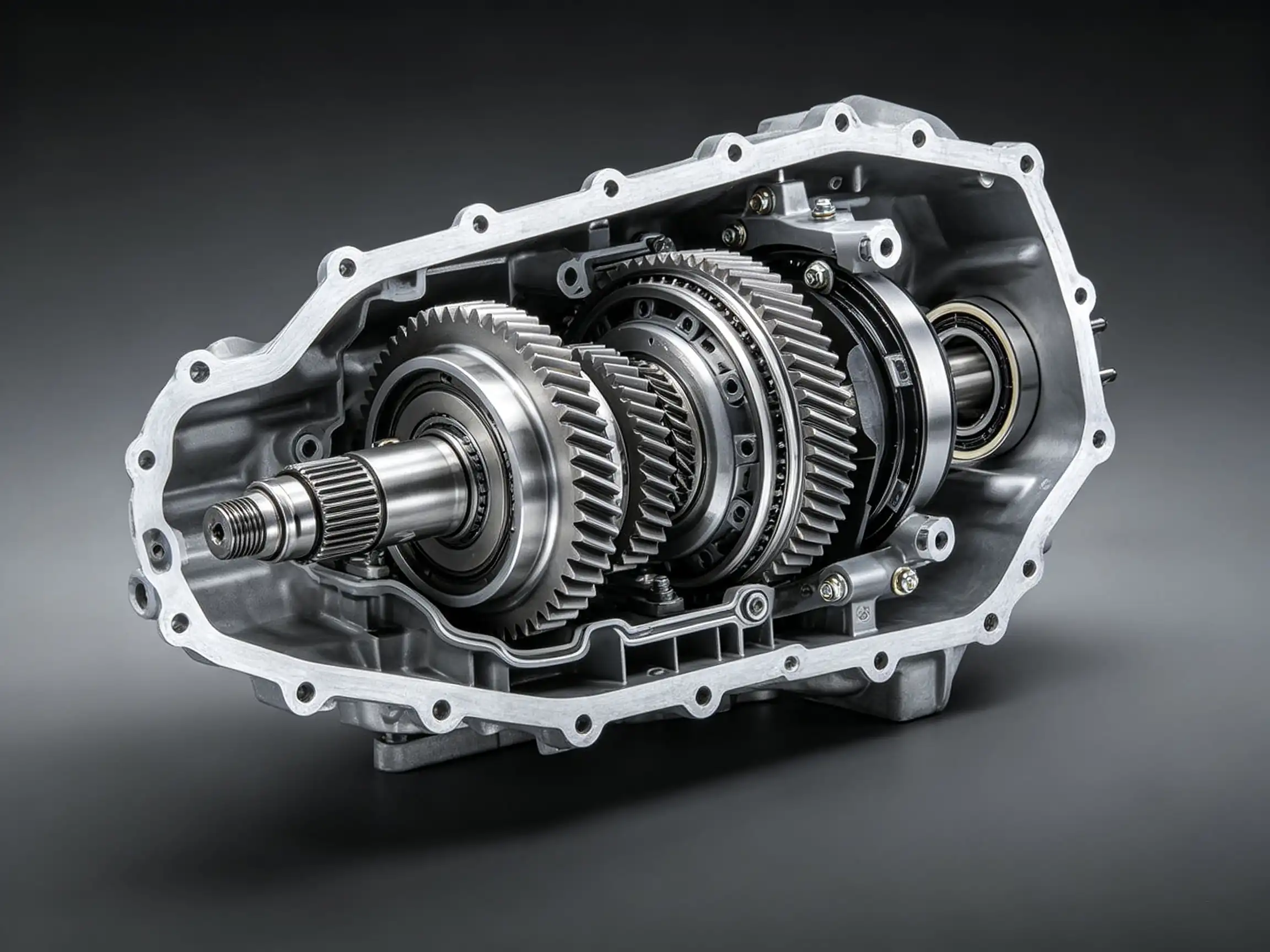
A helical gear shaft is an integrated transmission component that combines a helical gear and a drive shaft into a single solid piece. As a core solution for parallel-axis power transmission, it balances high rigidity, strong load capacity and low noise performance, making it well suited for medium-to-high speed, medium-to-heavy duty applications with strict requirements for drive smoothness.
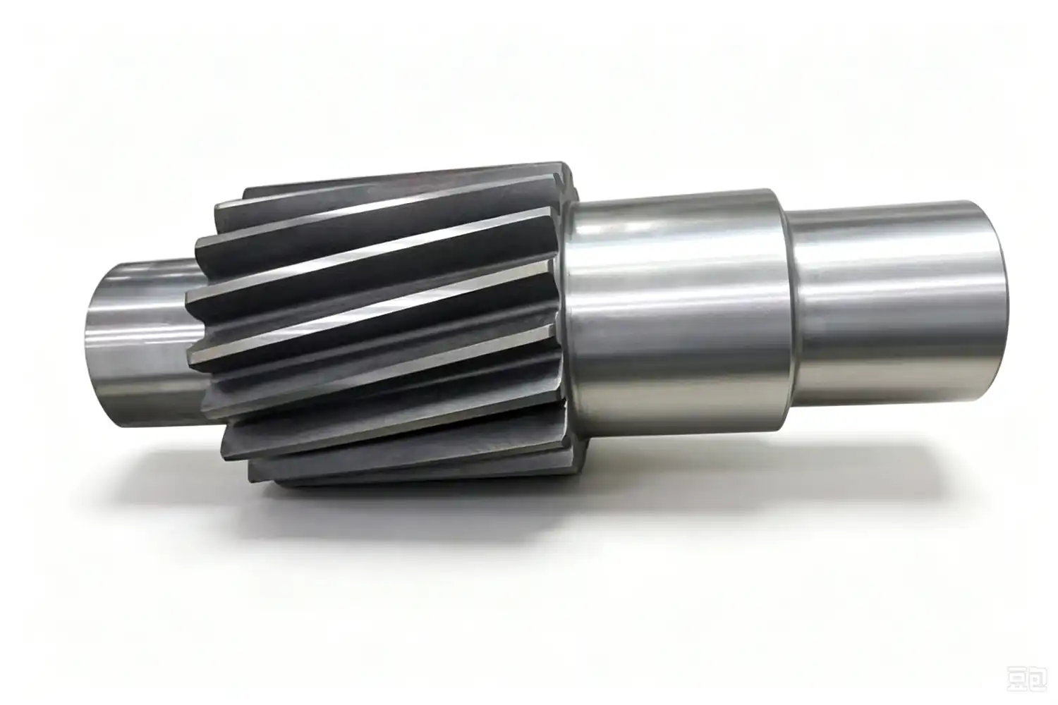
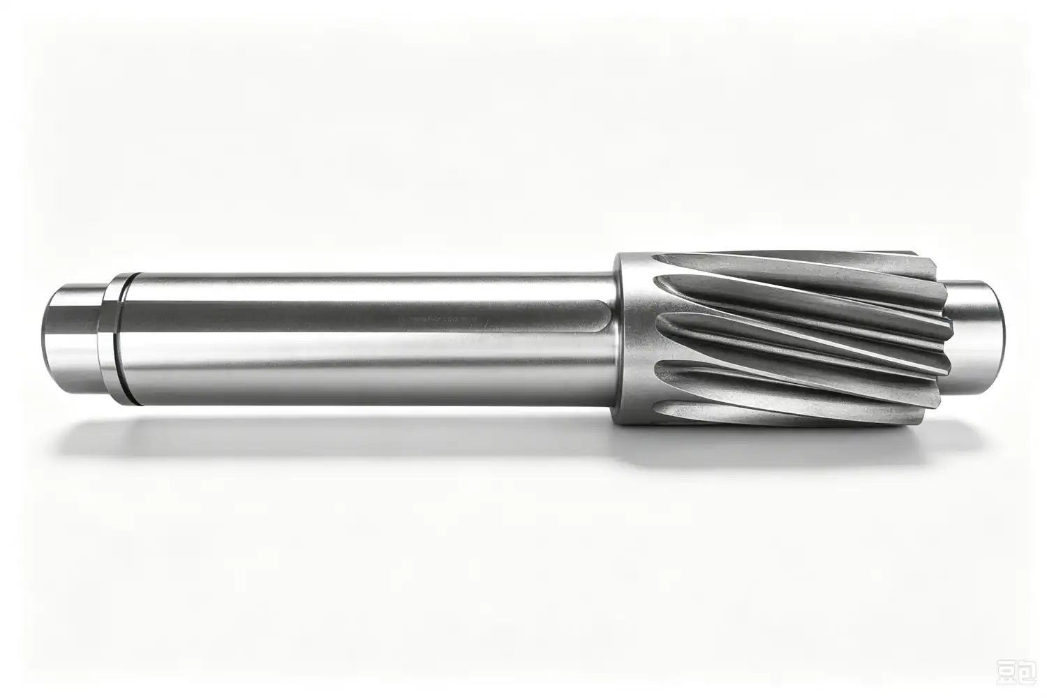
The gear teeth are machined directly into the outer surface of the shaft body, with their tooth traces forming a helix angle relative to the shaft axis. The one-piece shaft is fitted with standard mounting features at both ends, including support journals, drive keyways and positioning steps. In operation, teeth engage progressively along the full face width, delivering a higher contact ratio and smooth torque transfer between parallel shafts. In external mesh setups, the input and output shafts rotate in opposite directions.
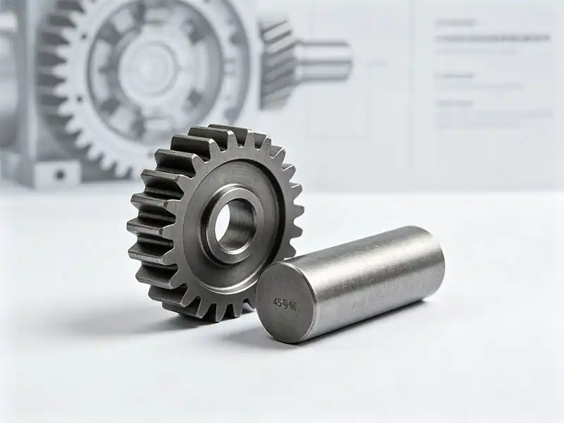
Compared with a conventional build using a separate helical gear pressed onto a drive shaft, this integrated design removes the need for key connections and shrink-fit assembly. It eliminates fit clearances and keyway failure risks at the source, delivers superior concentricity and transmission rigidity, and saves valuable installation space.
Next to straight-tooth gear shafts, helical gear shafts offer a smoother meshing action, lower vibration and noise, and higher load capacity. The tradeoff is that they generate axial thrust during operation and must be paired with thrust bearings; if the gear teeth sustain damage, the entire shaft requires replacement.
These components are widely deployed across precision gear reducers, CNC machine tools, industrial gearboxes, servo motors and new energy vehicle drivetrains — any equipment where smooth operation and compact space layout are key priorities.
2.Core Structure & Transmission Characteristics
1.Tooth Profile & One-Piece Integrated Design
It features a standard involute helical tooth profile with a nominal 20° pressure angle, and the tooth traces form a consistent helix angle relative to the shaft axis. The gear and shaft are machined from a single solid billet, eliminating separate assembly steps. This one-piece construction delivers superior concentricity and transmission rigidity, while its compact footprint saves valuable space inside equipment drive systems.
2.Meshing & Transmission Performance
Teeth engage and disengage progressively across the full face width, resulting in a significantly higher contact ratio than straight-tooth designs. This creates smooth, continuous power delivery with greatly reduced shock and vibration, lower operating noise, and a consistently accurate transmission ratio. By eliminating the backlash inherent in keyed connections, the integrated shaft delivers more immediate torque response — a particularly critical advantage in high-speed operating conditions.
3.Load Forces & Mounting Requirements
This is the defining difference between helical and straight-tooth gear shafts: meshing generates both radial and axial thrust forces simultaneously. For this reason, mating bearings must be selected to handle axial loads — such as angular contact ball bearings or tapered roller bearings — and the housing and support structure must be engineered for proper axial location. The one-piece shaft construction provides excellent torsional and bending strength, allowing it to withstand higher torque levels and combined loads.
4.Efficiency & Performance Boundaries
Mechanical transmission efficiency reaches 97–98.5%. Due to slight axial sliding between mating tooth surfaces, power losses are marginally higher than in straight-tooth gear shafts of equivalent precision. Its core strengths lie in high load capacity, smooth and quiet operation, and stable performance at high speeds. The tradeoffs are more demanding mounting requirements and slightly higher manufacturing costs compared with straight-tooth alternatives. It is best suited for medium-to-high speed, heavy-duty applications where noise control is a priority.
 +86 184 3796 0706
 info@destinytrans.com