CNC

Focusing on the design, manufacturing processes, heat treatment techniques, and key quality control points for all types of standard and non-standard gears.

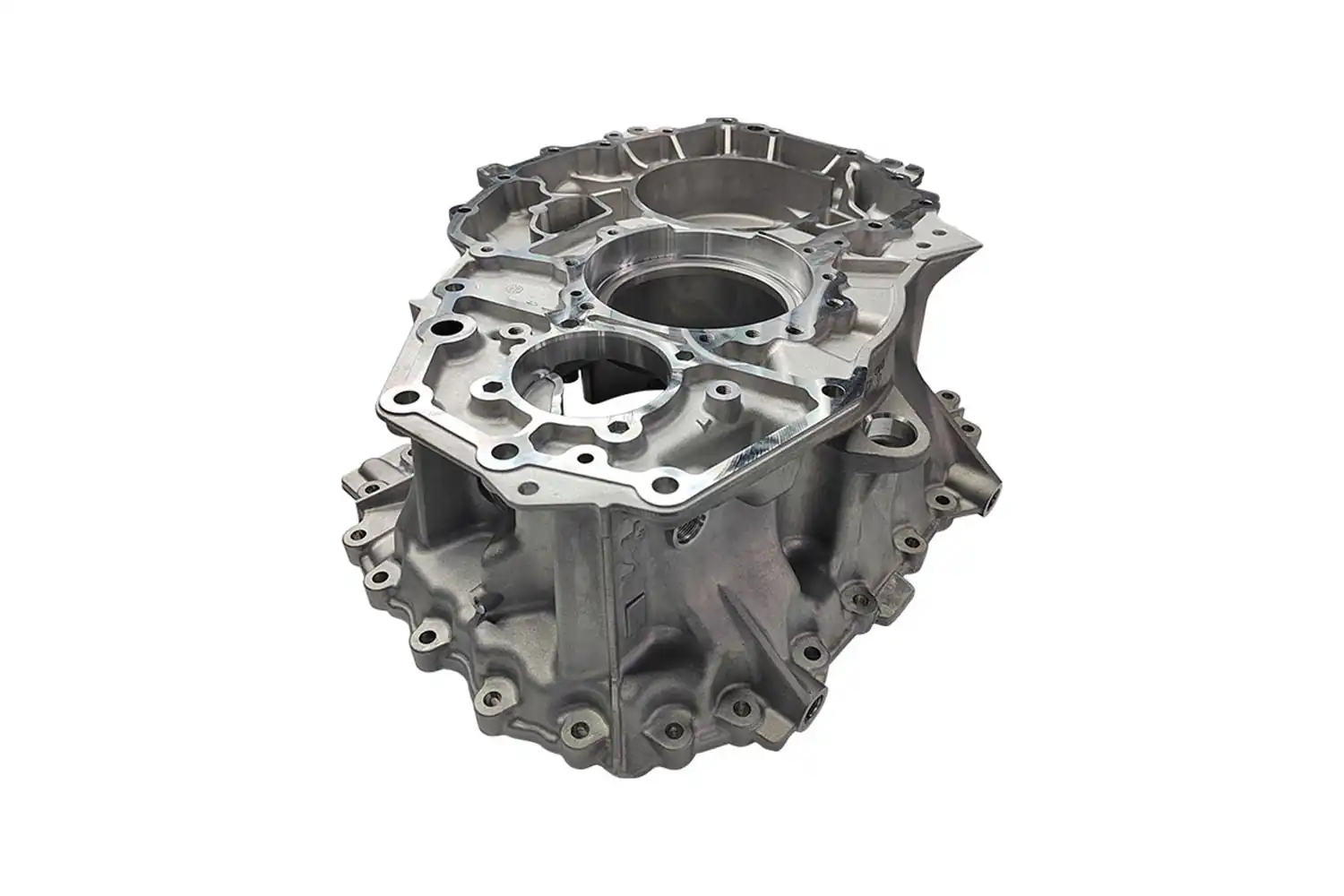
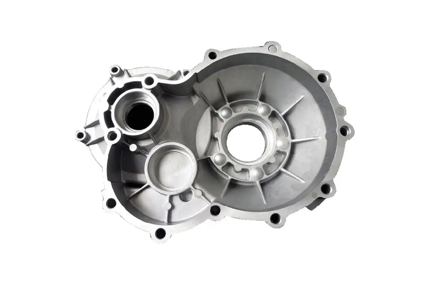
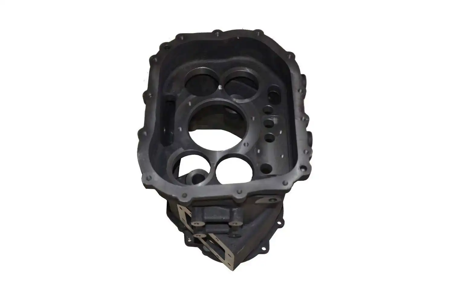
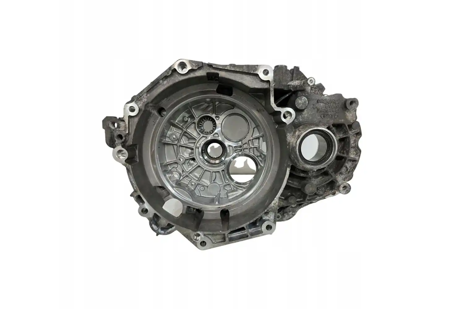
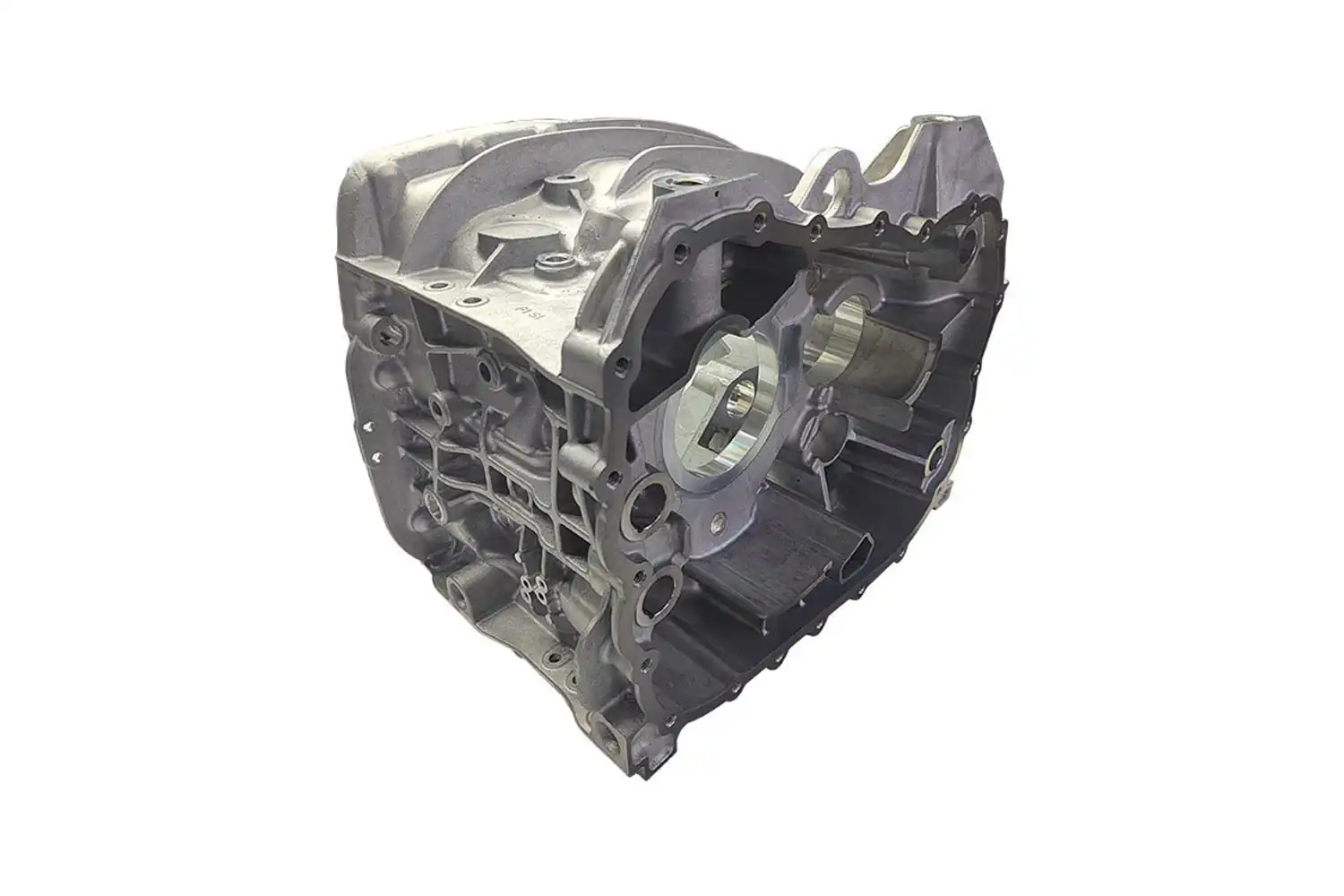
Custom Gearbox Housing CNC Machining

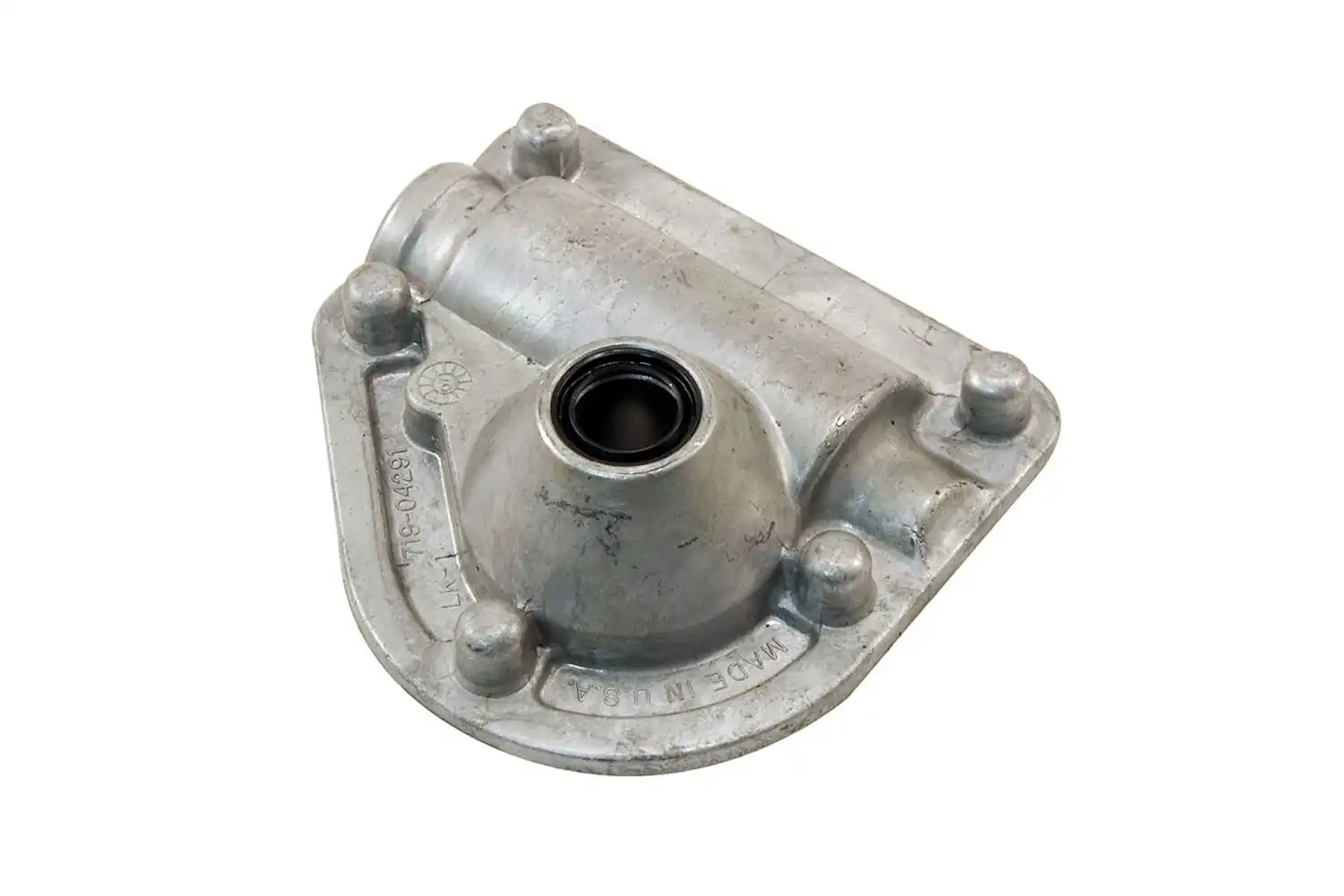
Gear reducer housings manufactured with end-to-end casting and CNC precision machining. Tight bearing bore concentricity tolerances, 100% pressure leakage tested per unit. Custom materials and configurations available for industrial power transmission applications.
Parameter Specification
Bearing Bore Concentricity ≤ 0.01mm
Pressure Leakage Test 0.3–0.8MPa, 100% per-unit inspection
Material Options Gray cast iron, ductile cast iron, cast steel, aluminum alloy
Supply Modes Raw casting blank, finish machining, full turnkey solution

Product Description

1. What is a Gear Reducer Housing?

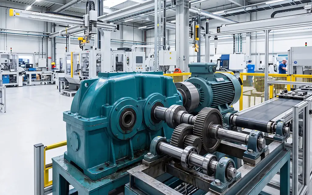
Also referred to as gearbox casings or reducer housings, these components form the load-bearing base and mounting datum for an entire gear reduction system.

They are far more than simple protective enclosures. Internally, the bearing bores, locating stops, and mounting datum surfaces directly dictate the assembly precision and mesh alignment of internal gears, shafts, and bearings. Externally, they provide secure mounting, load support, and environmental protection for the complete unit.

During operation, a housing must withstand radial and axial reaction forces as well as shock loads generated through power transmission, while maintaining enough rigidity to prevent deflection. It works alongside end covers and seals to create a closed lubricant cavity, dissipates heat from gear meshing via its walls and reinforcing ribs, and blocks out dust, moisture, and operating noise. Ultimately, it is the core structural component that defines the reducer’s overall transmission accuracy, running stability, and service life.

2. Core Features

Tight Geometric Tolerance Control

Critical bearing bores are fully machined — boring and milling — in a single setup, eliminating cumulative positioning error caused by multiple clamping operations. Concentricity is held to within 0.01mm, flatness of the mounting datum surface to ≤0.02mm, and bore pattern position tolerance to ≤0.015mm. This level of precision ensures proper meshing of all internal drive components, reducing operating noise and uneven tooth wear over time.

Structural Strength Tuned to Application

We optimize wall thickness and rib placement for each housing based on its specific load and duty cycle. Our standard material options, HT200 and HT250 gray cast iron, deliver excellent vibration damping and castability. For heavy-duty, high-impact applications, we offer ductile iron or cast steel grades. All materials are selected to resist alternating stress and shock loads, preventing housing deflection and joint face leakage over long service life.

Reliable Sealing and Environmental Protection

All mating faces and seal seats are precision machined to controlled surface roughness, delivering consistent, leak-tight oil chamber performance when used with standard seals. Every finished housing undergoes 100% air or hydraulic pressure testing to rule out leakage risks. For additional corrosion and environmental protection, surface treatments including shot blasting, liquid paint, and powder coating are available to suit outdoor, dusty, humid, and other harsh operating conditions.

Flexible, Customizable Configurations

We manufacture housings in multiple configurations: one-piece, horizontally split, and vertically split designs. Additional features such as mounting flanges, oil level ports, drain plugs, lifting eye threads, and inspection windows can be added to meet specific requirements. Designs are compatible with vertical, horizontal, and other common mounting arrangements.

3. End-to-End Manufacturing Capability

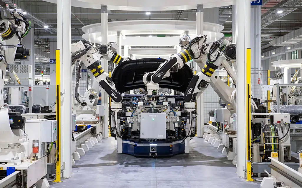
With our own in-house foundry and CNC machining facility, we deliver fully integrated production from raw casting to finished machined housing. This single-source approach cuts down on accuracy loss from multiple handling steps and streamlines communication for our customers.

  • Blank forming: We select the optimal casting process — sand casting, low-pressure casting, or others — based on material grade and order volume. After casting, all blanks go through stress relief annealing to remove internal residual stresses. Each blank is then visually inspected and non-destructively tested to catch sand inclusions, blowholes, and other casting defects before moving to machining.
  • Precision machining: Rough and finish operations are carried out on CNC lathes, vertical and horizontal machining centers, and boring mills. First-piece approval and in-process sampling checks are mandatory for all critical features, ensuring stable, repeatable dimensional and geometric tolerances throughout full production runs.
  • Finishing & quality assurance: All finished parts receive standardized deburring, sand removal, and cleaning. They pass through leakage testing and dimensional sampling before being released to inventory. Full CMM dimensional inspection reports can be provided at the customer’s request.

Parameter Information

Parameter Category Parameter Technical Specification
Machining Specifications Max Overall Dimension ≤1500mm (expandable upon request)
Housing Structure One-piece / split type; vertical / horizontal mounting available
Core Geometric Tolerances Bearing Bore Concentricity ≤0.01mm
Mounting Datum Surface Flatness ≤0.02mm per 1000mm
Bore Pattern Position Tolerance ≤0.015mm
Material & Forming Common Materials Gray cast iron, ductile cast iron, cast steel, aluminum alloy
Blank Process Cast forming + stress relief annealing
Performance Indicators Leakage Test 0.3–0.8MPa air / hydraulic test, 100% inspection per unit
Mating Surface Roughness Ra 1.6 – 3.2μm
Supply & Service Supply Options Raw blank, finished machining, full turnkey solution
Order Volume Support Single prototype, small-batch customization, mass production

Applications

Automotive & Powertrain
Industrial Automation & Robotics
Heavy Equipment, Mining & Construction
Industrial Reducers & Machinery

Standardized Production Process

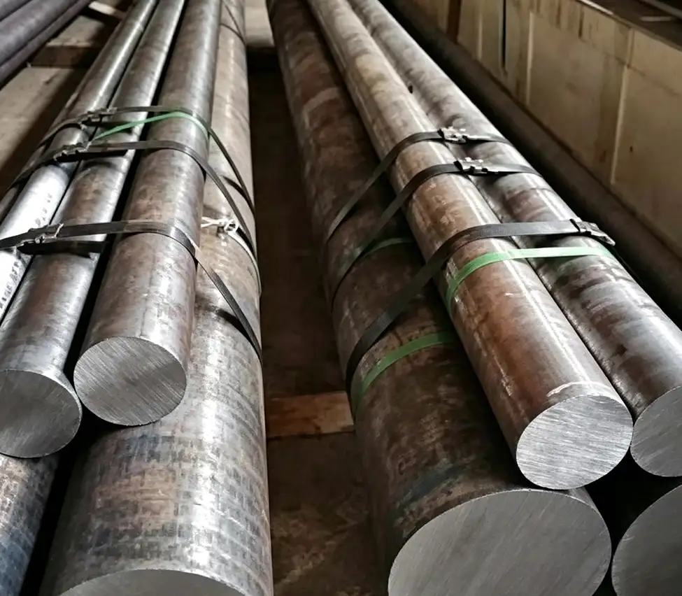
  1. Raw Material Verification & Preparation

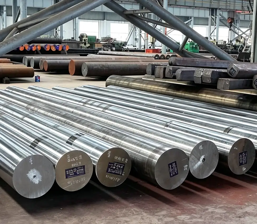
    Certified engineering steels (bars, forgings, or castings) are strictly verified with Mill Test Certificates (MTC). Ultrasonic flaw detection and chemical spectrometry are conducted before precision cutting to ensure flawless material integrity.

    01
  2. 02
    Rough Machining & Stress Relieving

    High-efficiency rough turning and milling remove bulk excess material to establish base reference planes. Intermediate thermal normalizing or stress-relieving annealing is applied to eliminate internal stresses and prevent subsequent machining distortion.

  3. Multi-Axis Precision CNC Machining

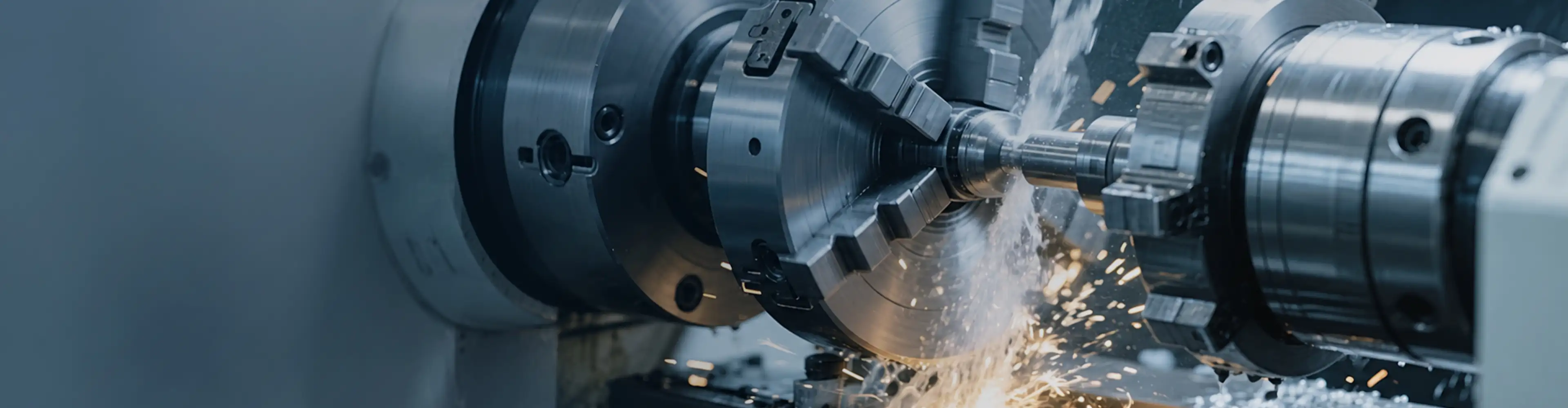
    Advanced 3-axis, 4-axis, and 5-axis CNC machining centers execute turning, milling, threading, and deep-hole drilling in single setups, establishing strict concentricity and complex geometries while reserving calculated allowances for post-treatment finishing.

    03
  4. 04
    Heat Treatment & Precision Finishing

    Controlled thermal processes (carburizing, quenching, or nitriding) optimize core toughness and surface hardness. Thermal micro-deformations are corrected via post-treatment precision grinding down to ±0.005 mm, followed by specified protective coatings.

  5. Full-Dimensional CMM Quality Inspection

    Comprehensive quality verification via Coordinate Measuring Machines (CMM), optical comparators, and surface roughness testers ensures full compliance with international GD&T standards. Verified FAI and pre-shipment inspection data accompany every batch.

    05
  6. 06
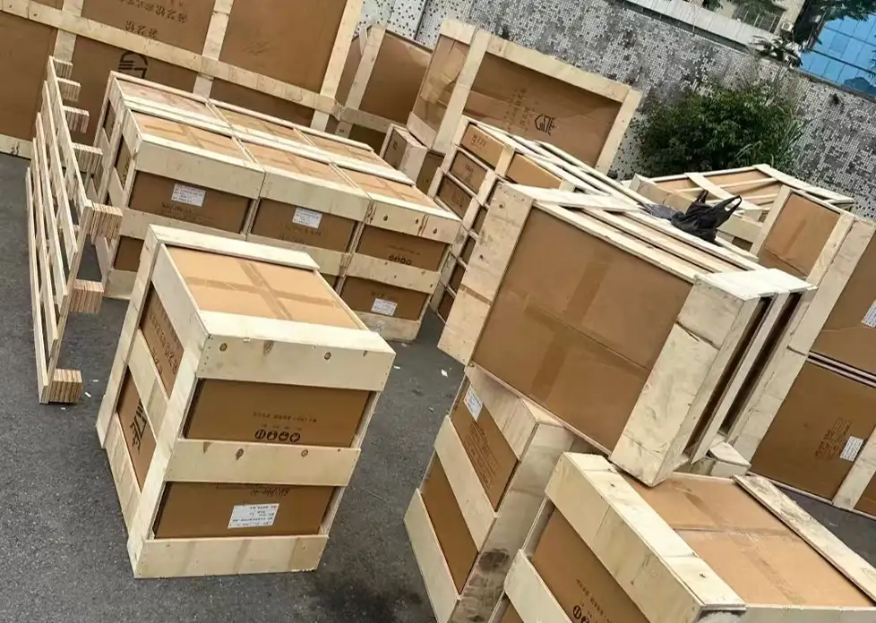
    Anti-Rust Preservation & Export Packaging

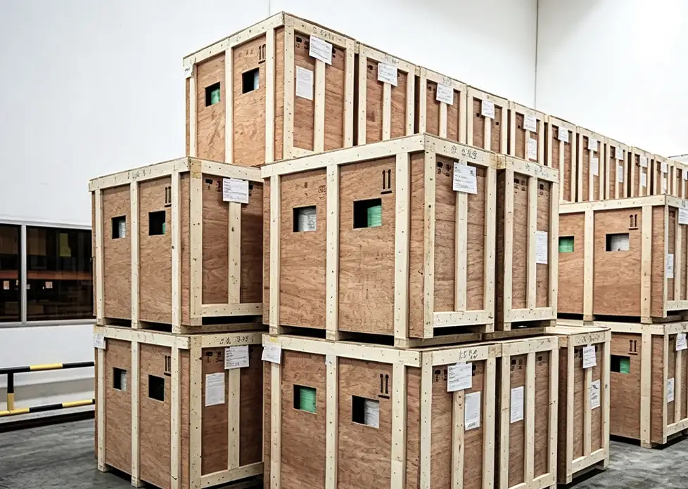
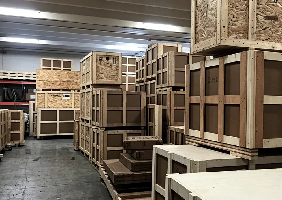
    Parts undergo ultrasonic cleaning, dehydration, and immersion in premium industrial anti-rust oil. Custom shock-absorbing materials (EPE foam/corrugated dividers) and fumigated wooden crates guarantee zero corrosion and transit safety worldwide.

Core Advantages

Micron-Level Precision & Complex Geometry

Equipped with high-end multi-axis CNC centers holding tight tolerances down to ±0.005 mm. Single-setup multi-tasking ensures superior concentricity, runout control, and flawless machining of intricate splines, bores, and contours.

Certified Metallurgy & Custom Heat Treatment

Strict raw material screening backed by verifiable Mill Test Certificates (MTC). Customized thermal processes—including carburizing, nitriding, and induction hardening—deliver an optimal balance between surface wear resistance and core impact toughness.

Closed-Loop GD&T Quality Assurance

Advanced quality verification via Coordinate Measuring Machines (CMM), optical profilers, and roughness testers. Full compliance with international GD&T standards, accompanied by First Article Inspection (FAI) and complete pre-shipment inspection data.

Agile Prototyping to Scaled Mass Production

Flexible manufacturing capacity supports rapid 1-piece prototyping or drawing replication up to continuous high-volume production. Direct-factory production guarantees tiered cost optimization, reliable lead times, and sea-worthy export protection.

Get In Touch

Materials Guide

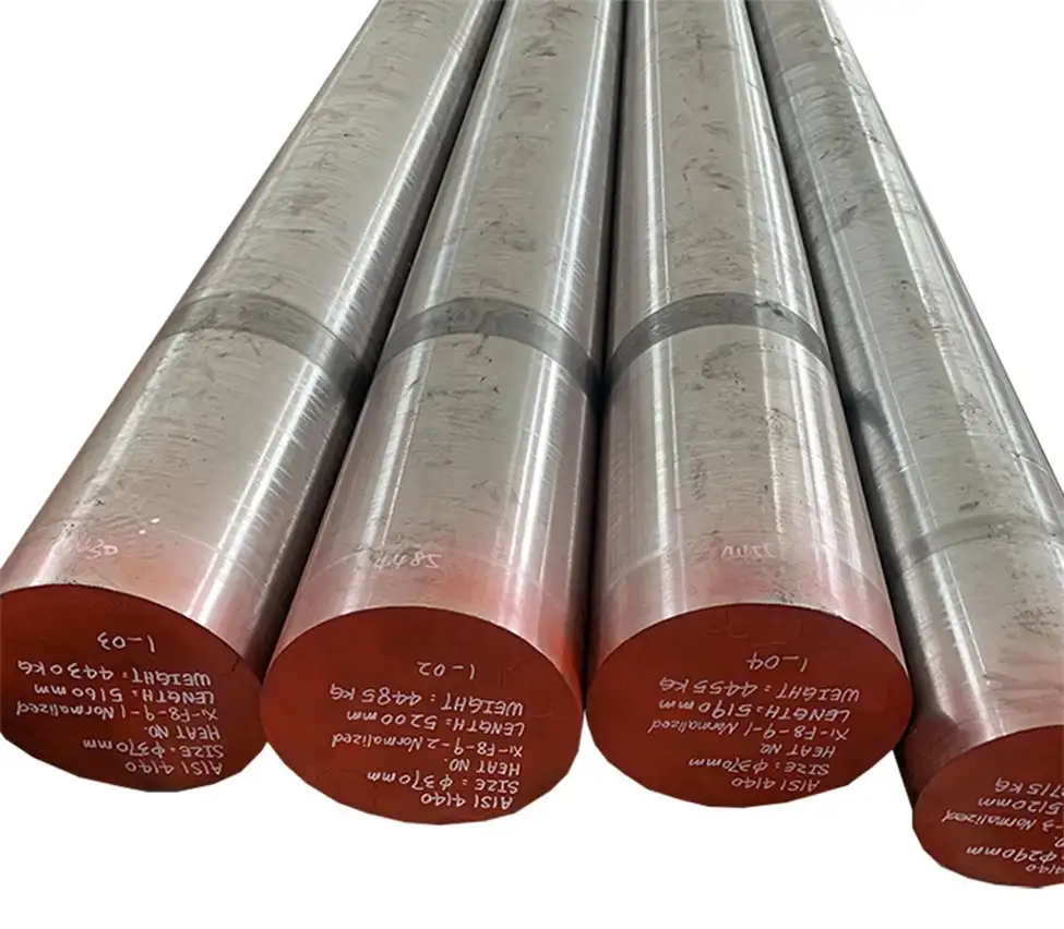
C45 / AISI 1045

C45 / AISI 1045

(Medium Carbon Structural Steel)

The benchmark engineering material for general mechanical parts, precision shafts, and structural components. Offers excellent machinability, dimensional stability, and balanced tensile strength. Responds reliably to normalizing, quenching & tempering (Q&T), and localized induction hardening for enhanced wear resistance.

42CrMo4 / AISI 4140

42CrMo4 / AISI 4140

(High-Tensile Alloy Structural Steel)

Engineered for heavy-duty transmission shafts, high-torque splines, and high-stress industrial components. Delivers superior toughness, fatigue resistance, and high torsional strength after quenching and tempering. Demonstrates minimal heat-treatment distortion and outstanding durability under severe impact loads.

16MnCr5 / AISI 8620

16MnCr5 / AISI 8620

(Case-Hardening Alloy Steel)

Optimized for components demanding superior surface wear resistance coupled with a shock-absorbing ductile core, such as integrated pinion shafts, cam lobes, and splined drive shafts. Deep carburizing delivers up to HRC 58–62 surface hardness while preventing brittle fractures under cyclic shock.

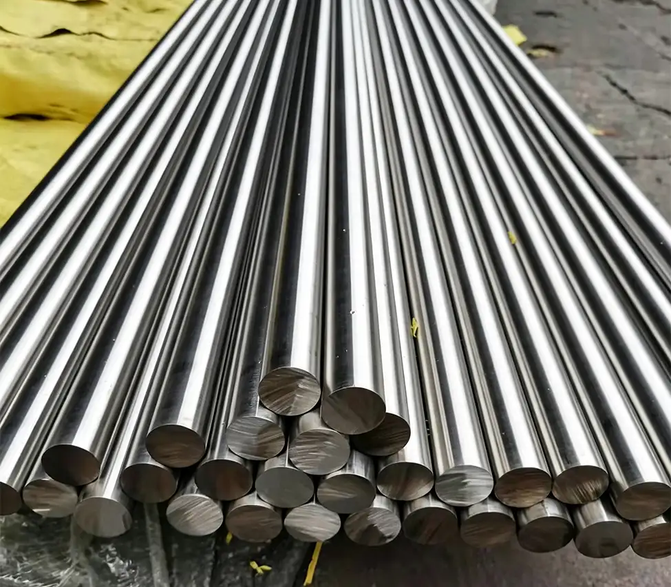
Stainless & Specialty Alloys

Stainless & Specialty Alloys

(Corrosion-Resistant Options)

Tailored for marine, chemical, food machinery, and severe corrosive environments. Combines exceptional oxidation resistance with tight-tolerance machinability. Grades like 17-4 PH (AISI 630) offer precipitation-hardened ultra-high yield strength for high-demand precision automation and aerospace-grade shafting.

Logistics & After-Sales Support

Logistics Support

Professional Anti-Rust Packaging

Cleaned ultrasonically, coated with high-grade anti-rust oil, and sealed in VCI barrier bags. Packed in custom shock-absorbing foam and ISPM-15 certified export wooden crates to prevent collision damage and moisture corrosion during ocean transit.

Global Delivery & Real-Time Tracking

Flexible support for EXW, FOB, CIF, and DDP terms with complete shipping documentation. Partnered with major sea and air carriers to provide real-time tracking and guarantee on-time delivery.

After-Sales Support

1-Year Warranty & Free Replacement

Every shipment includes verifiable MTC and CMM inspection reports. All machined parts carry a 1-year warranty; non-conforming components due to manufacturing defects are prioritized for free remanufacturing.

Rapid Engineering Support

Bilingual engineering team available via WhatsApp and email with <12-hour response times, offering assembly guidance, DFM cost optimization, and flexible batch scheduling for recurring orders.

Global logistics and shipping
Packing photo Packing photo Packing photo

Frequently Asked Questions (FAQ)

What CAD drawing formats do you require for quotation and production?

We accept 3D CAD files in STEP (.stp/.step), IGES (.igs), and Parasolid (.x_t) formats, accompanied by 2D engineering drawings in PDF, DWG, or DXF. 2D prints are essential for identifying critical tolerances, GD&T callouts, surface finish values, and tapped hole details.

What dimensional tolerances can your CNC machining achieve?

Our multi-axis CNC centers and CNC grinding machines achieve standard tolerances down to ±0.005 mm (±0.0002"). Precision shaft diameters, bearing journals, and ground gear teeth can meet IT5–IT6 tolerance grades and surface roughness down to Ra 0.4.

What is your Minimum Order Quantity (MOQ)? Do you handle rapid prototyping?

We have no rigid MOQ. We support rapid 1-piece custom prototyping and small pre-series test runs (10–50 pcs) to assist engineering validation, as well as scaled mass production with competitive tiered volume pricing.

What is your typical lead time for samples and production runs?

Standard rapid prototypes ship within 5 to 7 business days after drawing confirmation. Medium-to-large production runs typically require 2 to 4 weeks, depending on raw material availability, machining complexity, and heat treatment cycles.

What quality inspection reports and material certifications do you provide?

Every batch is backed by full traceability. We provide Mill Test Certificates (MTC / EN 10204 3.1), Coordinate Measuring Machine (CMM) full-dimensional inspection reports, First Article Inspection (FAI), and heat treatment hardness test sheets prior to release.

What heat treatment and surface finishing options are available?

We provide end-to-end thermal and finishing solutions, including carburizing & quenching, induction hardening, nitriding, and tempering, along with precision cylindrical grinding, black oxide, zinc/nickel plating, passivation, and phosphating.

How do you safeguard our intellectual property and proprietary drawings?

We enforce strict IP protection policies. We routinely sign mutually binding Non-Disclosure Agreements (NDAs) before reviewing any drawings. All customer data and proprietary engineering models are kept confidential on access-restricted internal servers.

Send Us a Message

Upload Drawing / Reference File

All drawings and technical information are kept strictly confidential and will never be disclosed to third parties.